
01
Replaceable Crushing Hammers and Tooth Segments
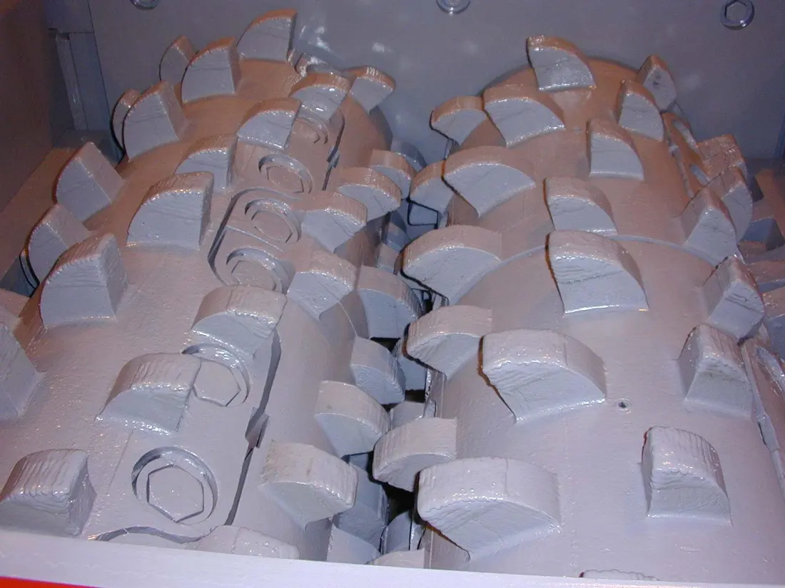
Crushing Hammers & Segments
Check scroll or flat tooth arrangements against the installation drawing, matching tooth height, roots, bolts and roll-body interfaces.
View Parts and Materials →For hard rock and clay-bearing ores — replaceable crushing hammers, tooth segments and optional breaker bars.
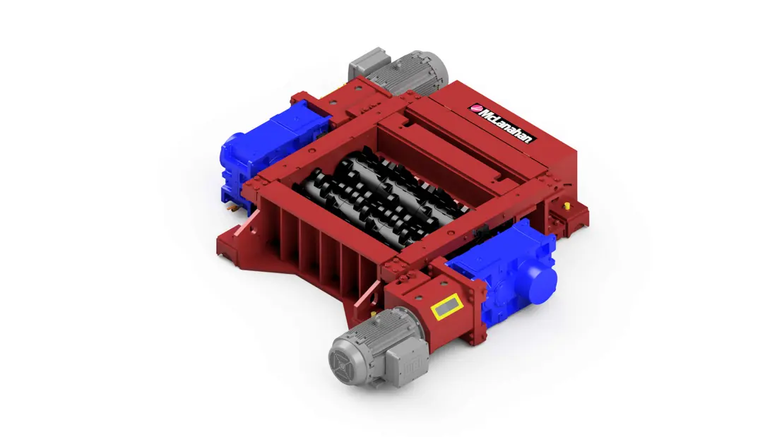
For primary and secondary crushing of hard rock, clay-bearing ores and selected battery minerals. This page covers the Mineral Sizer; explore the DDC-Sizer range for other primary, tertiary and fine-sizing configurations.
Roll width, tooth profile, drive orientation and breaker bar are project-specific. Provide the installation drawing when ordering.
| Configuration | Main Range | Parts Identification |
|---|---|---|
| Primary / Secondary Mineral Sizer | Published feed size up to 1,200 mm, reduced to approximately 300 mm | Roll diameter, width, gap and tooth drawings |
| Dual-drive Configuration | Parallel-shaft or right-angle arrangement | Left and right drives, gear ratio, torque and shaft-end interfaces |
| Breaker Bar (Optional) | Hydraulic height adjustment and removable design | Wear blocks, mounting interfaces, adjustment shims and cylinders |
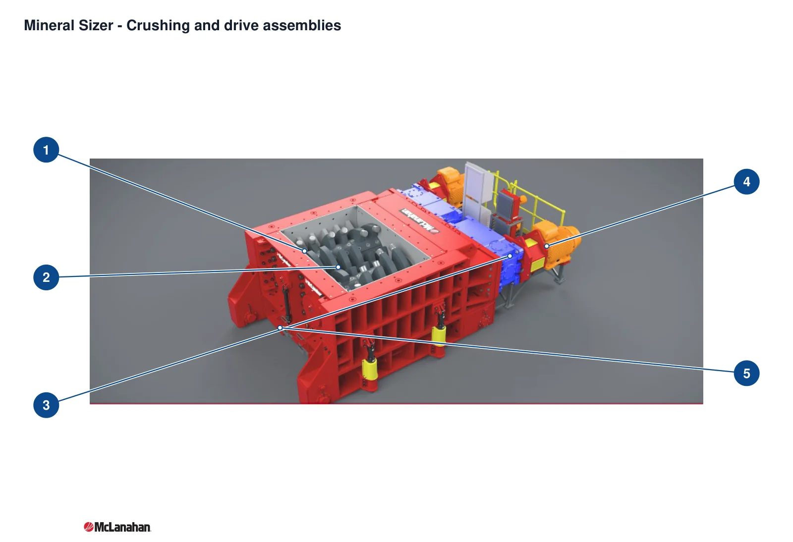
The numbers on the diagram correspond one to one with the rows below.
| No. | Component | Location | Applies to |
|---|---|---|---|
| 1 | Crushing hammer | Crushing hammers on the rolls inside the open chamber | Mineral Sizer |
| 2 | Crushing roll assembly | The two inward-rotating rolls inside the chamber | Mineral Sizer |
| 3 | Gear reducer | Blue gear reducer behind the crushing frame | Mineral Sizer |
| 4 | Drive motor | Orange drive motor outboard of the reducer | Mineral Sizer |
| 5 | Main frame | Red main frame around the crushing chamber | Mineral Sizer |
Material selection considers tooth-body toughness, surface wear and repair welding. Different positions may require different grades.
Crushing Hammers & Segments
Check scroll or flat tooth arrangements against the installation drawing, matching tooth height, roots, bolts and roll-body interfaces.
View Parts and Materials →Breaker Bar Wear Segments
Located below and between the rolls to restrict slabby material. Match the breaker bar assembly drawing, clearances and hydraulic fastening interfaces.
Send Breaker Bar Drawings →Frame Liners & End Plates
Check liner sections, thickness, hole spacing and impact faces while preserving maintenance access.
View Parts and Materials →Match mechanical drive parts and hydraulic equipment to the installed configuration.
Roll Shafts & Bearing Supports
Check left and right shafts, segment interfaces, bearing fits and removal direction.
View Parts and Materials →Dual Drives & Couplings
Check parallel or right-angle arrangement, gear ratio, input and output interfaces, and rated torque.
View Parts and Materials →Segment Fasteners
Match thread, strength class, grip length and locking design; do not mix similar but different specifications.
View Parts and Materials →Breaker Bar Hydraulics & Tramming Parts
The optional breaker bar uses cylinders and shims for adjustment. Check tramming rails, drives and hydraulic locating pins separately.
Send Hydraulic and Tramming System Details →The OEM Mineral Sizer design allows hammer or segment replacement without removing the roll shaft. Follow the maintenance manual for the installation; removal procedures differ between Sizer ranges.
Provide the model, serial number, photographs of the existing part, any known drawing and critical dimensions. ANRANST provides drawing and engineering review, production at certified foundries, in-factory inspection and finished-part delivery. OEM names identify equipment and do not imply OEM authorization.
Or contact us directly: +86 156 3797 3199
zzx@anranst.com
ANRANST provides customers worldwide with engineering assessment, production at certified foundries to the customer technical requirements, quality control and finished-part delivery for custom wear parts and industrial spares, with scope to support other custom industrial parts.
We review mating surfaces and interface dimensions and assess material, heat treatment and manufacturing feasibility.
Material grades and heat-treatment processes are specified order by order, stated in the technical agreement and tracked through production.
Drawing confirmation, material and process control, production tracking, inspection and acceptance coordination.
We coordinate manufacturing, quality confirmation, packaging and delivery of complete finished parts in a workable, closed-loop supply process.
Provide the existing model, drawings, drawing, materials or operating conditions so we can identify the appropriate technical review and supply route.
Submit an Enquiry