McLanahan Feeder-Breakers

Surface stationary/mobile and underground crawler-mounted configurations: review capacity, product size, picks, flight chains, shafts and direct-drive spares together.

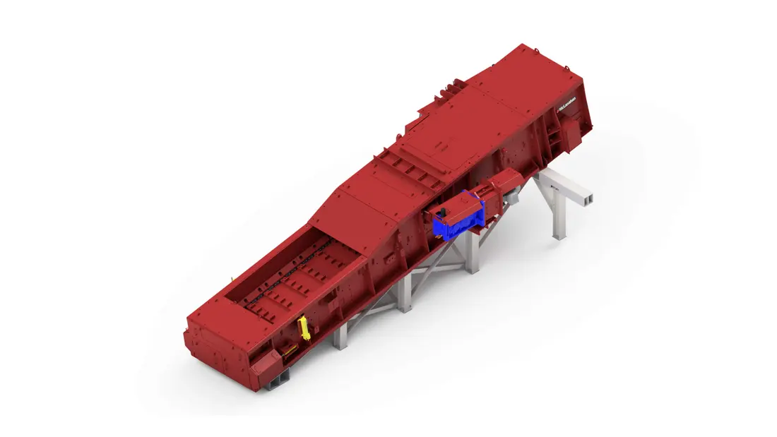
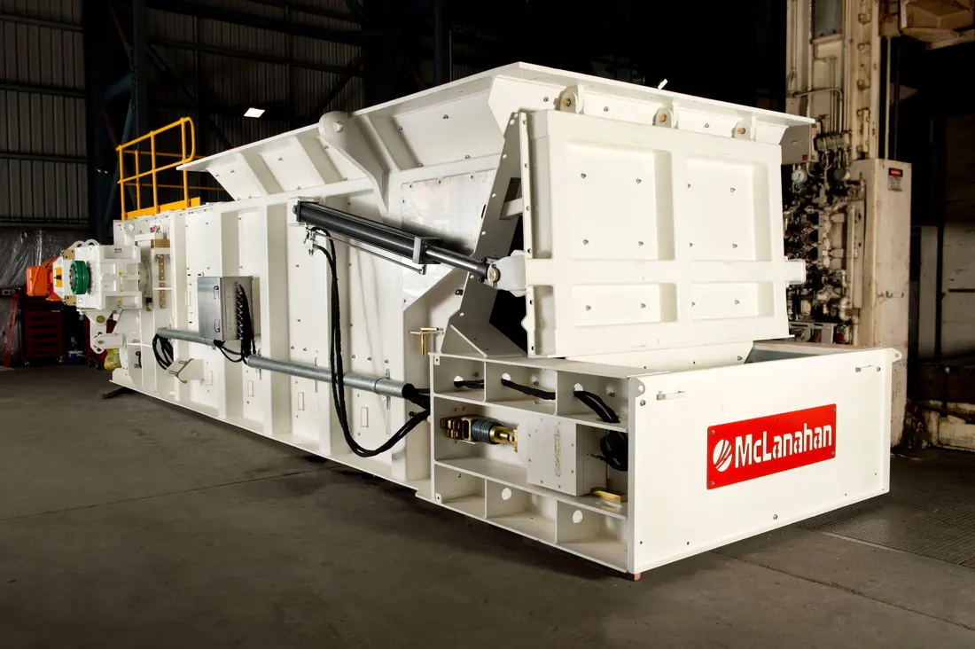
McLanahan stationary/mobile feeder-breaker, official photograph
Official McLanahan stationary/mobile feeder-breaker photograph, showing the receiving hopper, trough, breaking end and drive configuration.
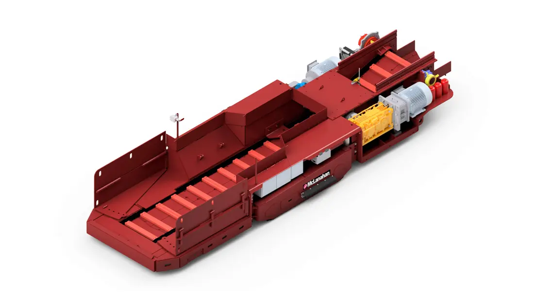
McLanahan crawler-mounted feeder-breaker, official image
Official McLanahan underground crawler-mounted feeder-breaker image. Confirm crawlers, chain conveyor and breaking drive against the project configuration.
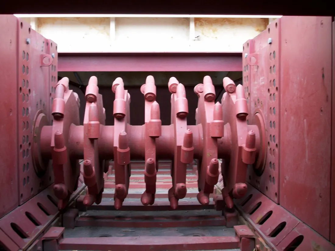
McLanahan feeder-breaker roll picks, official close-up
Official McLanahan breaker-roll close-up. Picks, holders, retainers and the roll shaft are key identification points.
OEM Equipment Reference

Identify Wear Parts and Flight-Chain Spares for Both Current Configurations

McLanahan publishes Stationary/Mobile and Crawler-Mounted feeder-breaker configurations rather than one fixed model code system. This page retains ranges directly relevant to picks, liners, flight chains, shafts and drive spares. Before manufacture, check nameplate, serial and project numbers, general arrangement, drawings and used parts.

2Current official configuration families
6,000 tphPublished maximum surface-model capacity
1,200 tphPublished maximum crawler-model capacity
150–300 mmPublished typical one-dimensional product range
Standard Models and Key Dimensions

Current McLanahan Feeder-Breaker Configurations and Ranges

The catalogue separates surface stationary/mobile and underground crawler-mounted configurations. Capacity and product size are selection ranges, not evidence that chains, breaker rolls or drives interchange across projects.

Current configuration familyInstallation and conveying arrangementPublished key rangeSpare-part checks
Stationary / Mobile Feeder-BreakersFixed, skid-mounted, towable on unpowered crawlers or powered crawler-mounted; single or twin flight conveyorsUp to 6,000 tph (5,400 mtph); typical one-dimensional product size 150–300 mmReceives trucks, loaders or dozers; check hopper capacity, chain pitch, trough width, breaker-roll height and drive configuration
Crawler-Mounted Feeder-BreakersUnderground crawler-mounted unit advancing with the face and belt lineUp to 1,200 tph (1,080 mtph); typical one-dimensional product size 150–200 mmCheck seam height, receiving method, chains and flights, breaker roll, crawlers, remote controls, fire protection and dust suppression
Parts within one configuration vary with feeding method, hopper capacity, trough width, single/twin conveyors, product size, drive and mobile chassis. The name “Feeder-Breaker” alone is not a manufacturing specification.
McLanahan

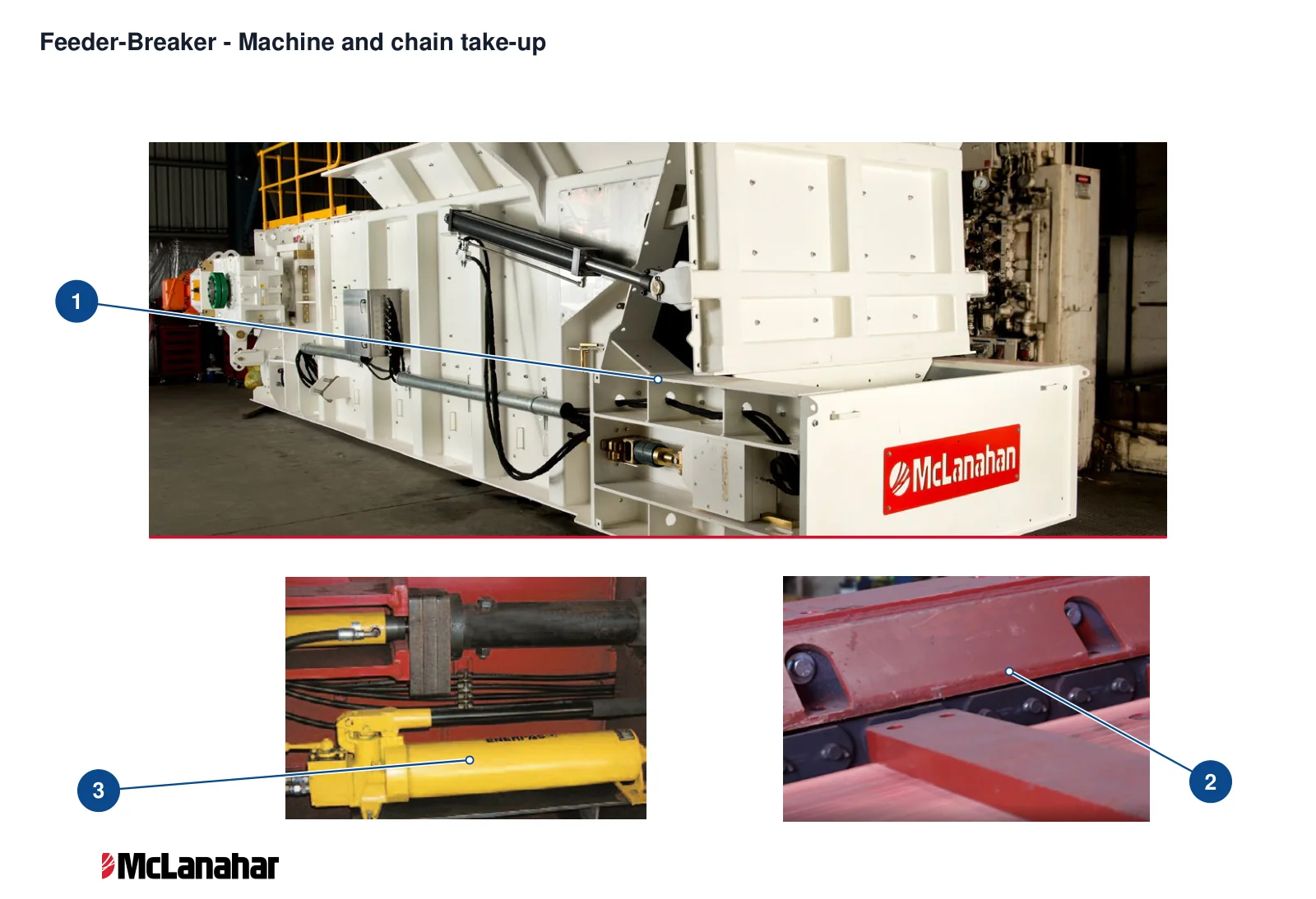
Component Location Diagram

The numbers on the diagram correspond one to one with the rows below.

McLanahan Feeder-Breakers – Component Location Diagram
Pictured model: Feeder-Breaker
No.ComponentLocationApplies to
1Main frameWhite load-bearing feeder-breaker frameFeeder-Breaker
2Conveyor chainBlack chain links behind the red flights in the OEM Chain Conveyor close-upFeeder-Breaker
3Chain take-up cylinderHydraulic cylinder in the lower-left Chain Take-Up imageFeeder-Breaker
Wear Parts

Picks, Deck Liners, Hopper Protection and Flight Wear Parts

Separate wear parts by actual breaker-roll, deck, hopper-wall, flight and guide positions. Materials and processes support preliminary assessment; original drawings and acceptance requirements govern the final choice.

McLanahan feeder-breaker deck and breaking area, official rendering
03

Crushing-Zone Deck Liners

Crushing-Zone Deck Liner

Flights drag material along the steel deck. The crushing-zone deck takes concentrated impact and sliding wear. The manufacturer's design uses replaceable wear plate plug-welded to the base plate.

View the common part page →
McLanahan feeder-breaker chain and flight working area, official rendering
05

Solid Alloy-Steel Flight Bars

Solid Alloy Steel Flight Bar

Flights connect the two engineering-class chains and drag material across the deck and breaking zone. Check trough width, flight section, chain spacing, connecting holes, direction and minimum clearance to the breaker roll.

View the common part page →
Spare Parts

Flight Chains, Head and Tail Shafts, Breaker Rolls and Direct Drives

Engineering chains, sprockets, head and tail shafts, breaker rolls, gear reducers and hydraulic drives require complete installation interfaces, left/right positions and project configurations.

McLanahan feeder-breaker side chains, official rendering
01

Engineering-Class Roller Chains and Connectors

Engineering-Class Roller Chain & Connector

The two side chains and solid flights form the conveyor assembly. Check chain pitch, plate thickness, pins and bushings, tensile rating, connecting links, left/right pairing and total link count.

View the common part page →
McLanahan feeder-breaker breaking and conveying direct drives, official rendering
05

Right-Angle Reducers and Torque-Limiting Couplings

Right-Angle Reducer & Torque-Limiting Coupling

The breaker roll uses a shaft-mounted right-angle reducer and torque-limiting coupling. The conveyor head shaft may use the same mechanical arrangement. Distinguish breaking and conveying drive ratios, torques and interfaces.

View the common part page →
FAQ

Frequently asked questions

Can picks, flight chains and sprockets be ordered by equipment name alone?

No. Check serial and project numbers, trough width, chain pitch, tooth profile, breaker-roll position, head/tail shaft interfaces, drive configuration, drawings and used-part dimensions.

Submit Feeder-Breaker Nameplate, Project Number, Drawings and Used-Part Details

Provide installation type, full nameplate, serial and project numbers, trough width, chain pitch, flight and pick photographs, breaker-roll position, drawings, used-part dimensions, materials and feed conditions. We use these for identification, material assessment, manufacturing coordination, quality control and delivery.

Equipment Brand and ModelDrawingDrawing or DimensionsCurrent MaterialPhotographs of Failed PartsTarget Service LifeOperating Conditions
Request a Quote

Or contact us directly: +86 156 3797 3199
zzx@anranst.com

Manufacturing Services in China

From Technical Assessment to Finished-Part Delivery

ANRANST provides customers worldwide with engineering assessment, production at certified foundries to the customer technical requirements, quality control and finished-part delivery for custom wear parts and industrial spares, with scope to support other custom industrial parts.

01

Drawing and Engineering Review

We review mating surfaces and interface dimensions and assess material, heat treatment and manufacturing feasibility.

02

Material and Heat-Treatment Specification

Material grades and heat-treatment processes are specified order by order, stated in the technical agreement and tracked through production.

03

Quality Control

Drawing confirmation, material and process control, production tracking, inspection and acceptance coordination.

04

Finished-Part Delivery

We coordinate manufacturing, quality confirmation, packaging and delivery of complete finished parts in a workable, closed-loop supply process.

Provide the existing model, drawings, drawing, materials or operating conditions so we can identify the appropriate technical review and supply route.

Submit an Enquiry