
VERTICAL STIRRED MILL WEAR SYSTEM
Tower Mill and Vertical Stirred Mill Wear Parts
Protection for agitators, rotors, stators, mill bodies, bases, retention screens and flow paths
Screw-type millsScrew wear liners, end liners, shaft liners and wear caps
Rotor–stator millsRotors, stator rings and internal working clearances
Mill body and flow pathsBody, base, feed and discharge passages, and retention screens
Identification requirementsOEM, full model designation, direction of rotation, dimensions, drawing and grinding media
Mill Design and Configuration Equipment identification OEM, series, full model designation, power rating and manufacturing revision Stirring mechanism Screw, disc or rotor–stator design; stage count, direction of rotation and interfaces Working clearances Agitator-to-body, rotor-to-stator, bottom and screen clearances Grinding conditions Grinding media, slurry, particle size, solids concentration, speed, power and throughput
Identify the stirring mechanism before specifying individual wear parts
Equipment described as a tower mill, vertical mill or vertical stirred mill may use a permanent screw with replaceable liners, integral or segmented agitators, or multiple rotor–stator stages. Similar names do not establish parts interchangeability.
Stirring-System Wear Parts
Identify screw and rotor–stator designs separately
These parts transfer energy directly. Their profiles, clearances and remaining thickness affect grinding efficiency and protection of the permanent structure.
Screw-type equipment Screw / Impeller / Agitator
Circulates grinding media and slurry. Distinguish the permanent structure from replaceable wear parts, and verify diameter, pitch, direction of rotation, interfaces and dynamic balance.
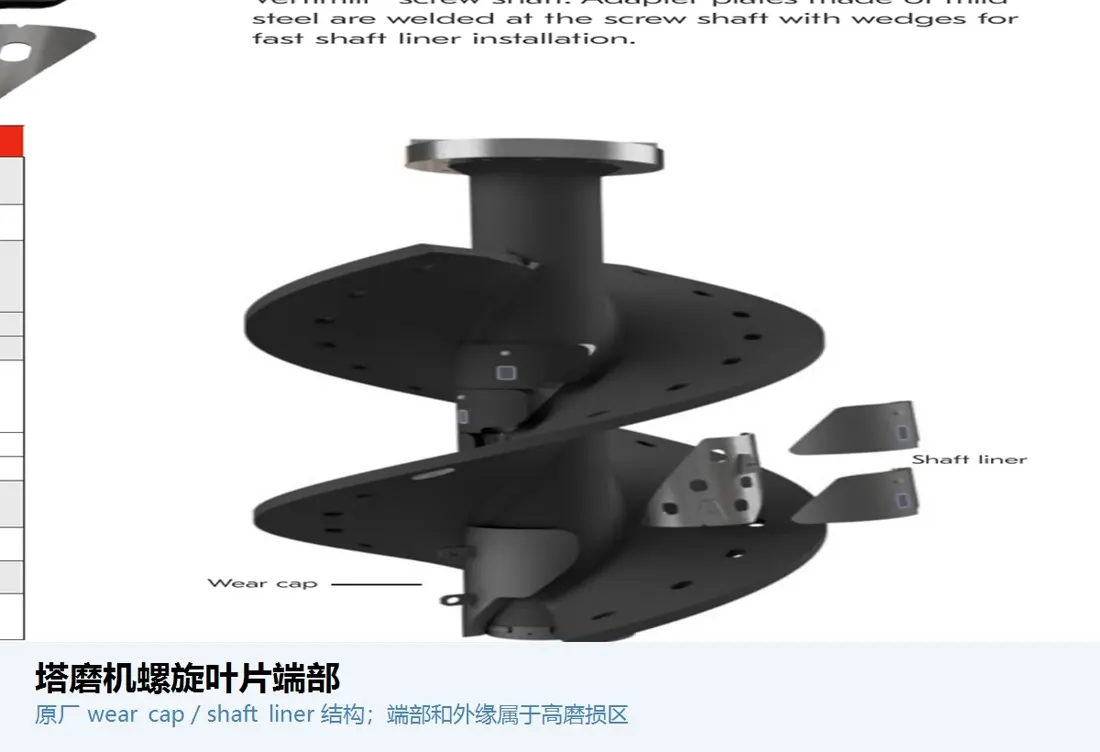 High peripheral-speed edges
 Screw Tips / Flight Tips
Protect the outer edges and ends of the screw flights. Peripheral speed, media pressure and wear are generally higher here. Confirm the tip profile, attachment and remaining thickness of the supporting structure.
 Rotor–stator equipment
 Stirring Rotor
Transfers energy to the grinding media in the applicable mill design. Confirm the OEM model, stage count, shaft interface, outside diameter, direction of rotation, adjacent stator and working clearance.
 Rotor–stator equipment
 Stator Ring
Works with the rotor to form the grinding zone. Internal diameter, thickness, fastening, position between stages and clearance after wear must be checked together with the rotor.
Permanent drive structure Main Shaft
Supports the agitator and transmits torque. The main shaft is not an ordinary wear part. Verify shaft shoulders, splines or flanges, straightness, material, heat treatment and non-destructive testing.
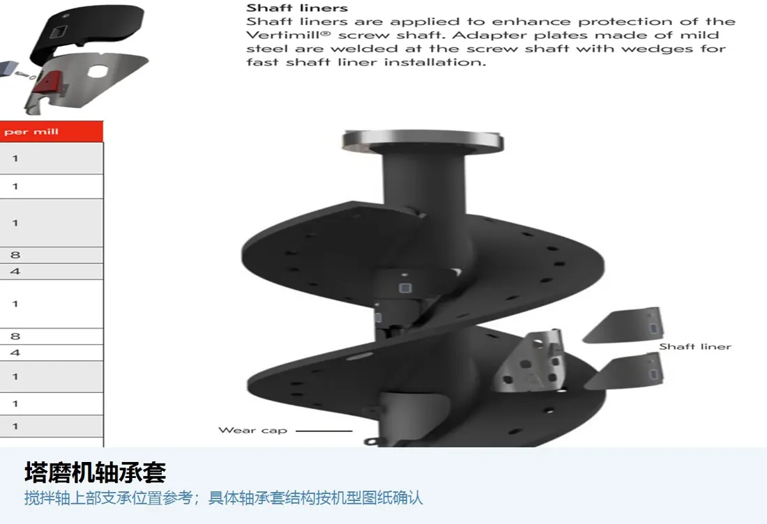 Support and replaceable interfaces
 Bearing Bushing / Shaft Sleeve
Protects the shaft or provides a bearing mating surface. Specify by shaft diameter, housing bore, fit, lubrication, material, surface condition and coaxiality.
Mill Body, Base and Flow Paths
Protect the permanent mill structure and maintain media and slurry flow paths
The body, base, feed, discharge and separation arrangements face different abrasive particles, velocities, pressures and maintenance conditions.
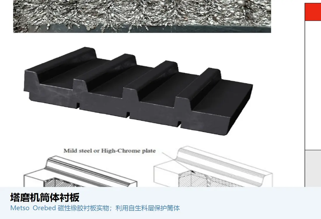
Mill inner wall Shell Liners
Protect the inner wall and maintain working clearances. Check segmentation, internal diameter, thickness, access-door area, fastening, grinding media and allowable wear limits.
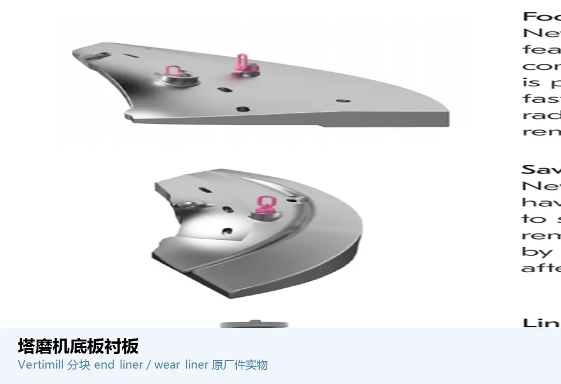 Mill bottom
 Base Plate / Base Liner
Withstands accumulated media, circulation and local erosion. Check the central arrangement, draining provisions, agitator-end clearance, thickness and fastening.
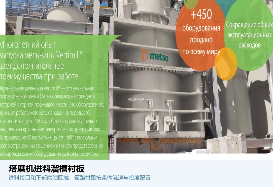 Feed flow path
 Feed Chute Liner
Protects the feed inlet and transition passage. Select materials for feed size, slurry conditions, drop height, flow direction, interfaces and maintenance access.
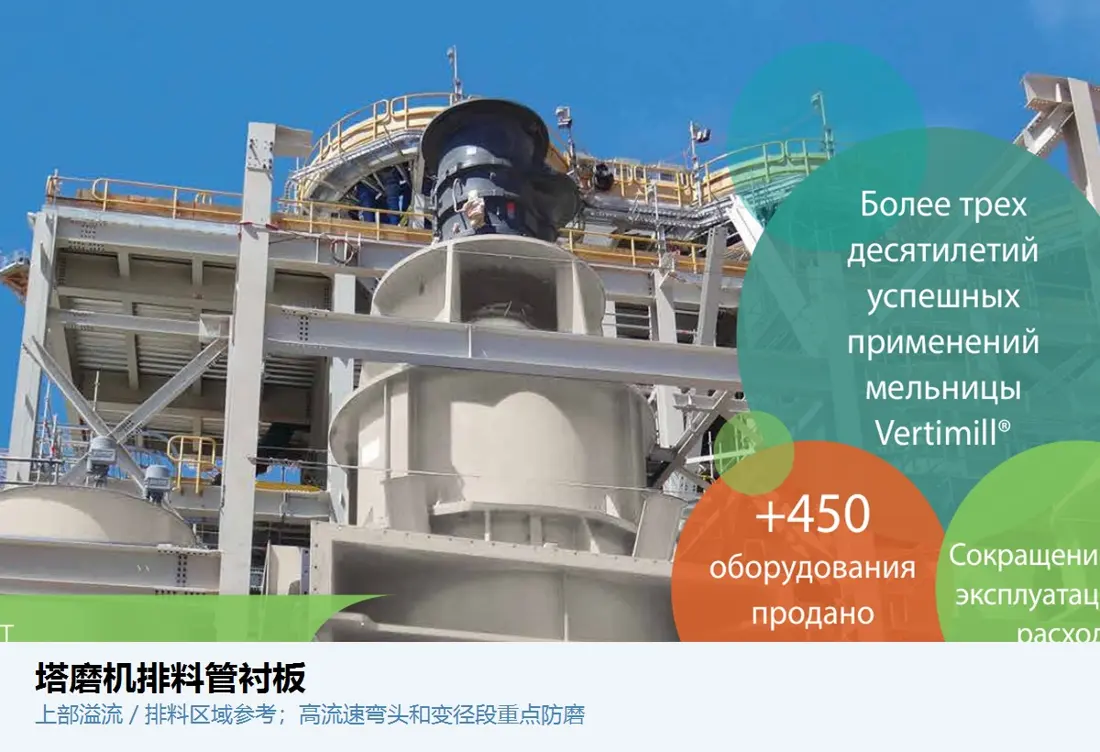 Discharge flow path
 Discharge Pipe / Passage Liners
Withstand continuous erosion by fine-particle slurry. Verify internal diameter, bends, flanges, flow velocity, solids concentration, pressure and lining continuity.
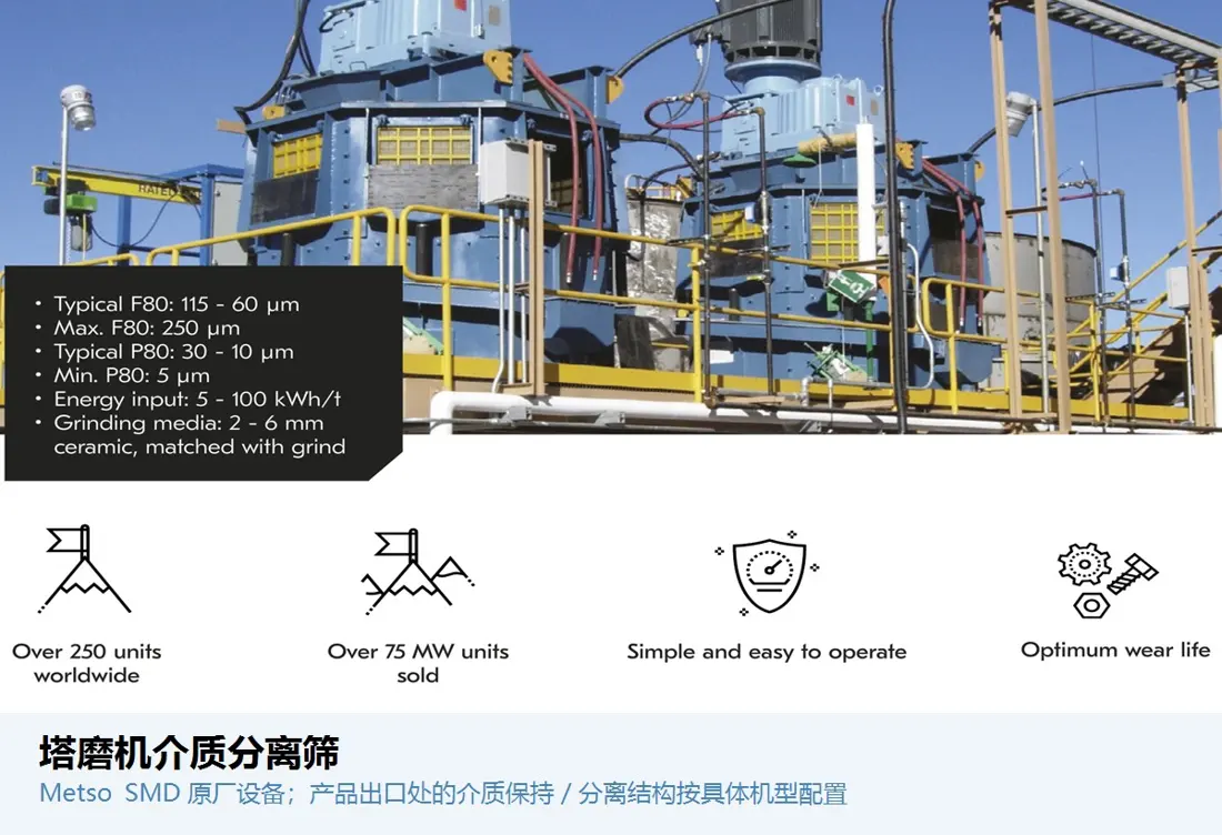 Media retention
 Media Retention Screens
Allow product to leave while retaining the grinding media. Check slot size, open area, material, support, blinding and differential pressure against media size and product particle size.
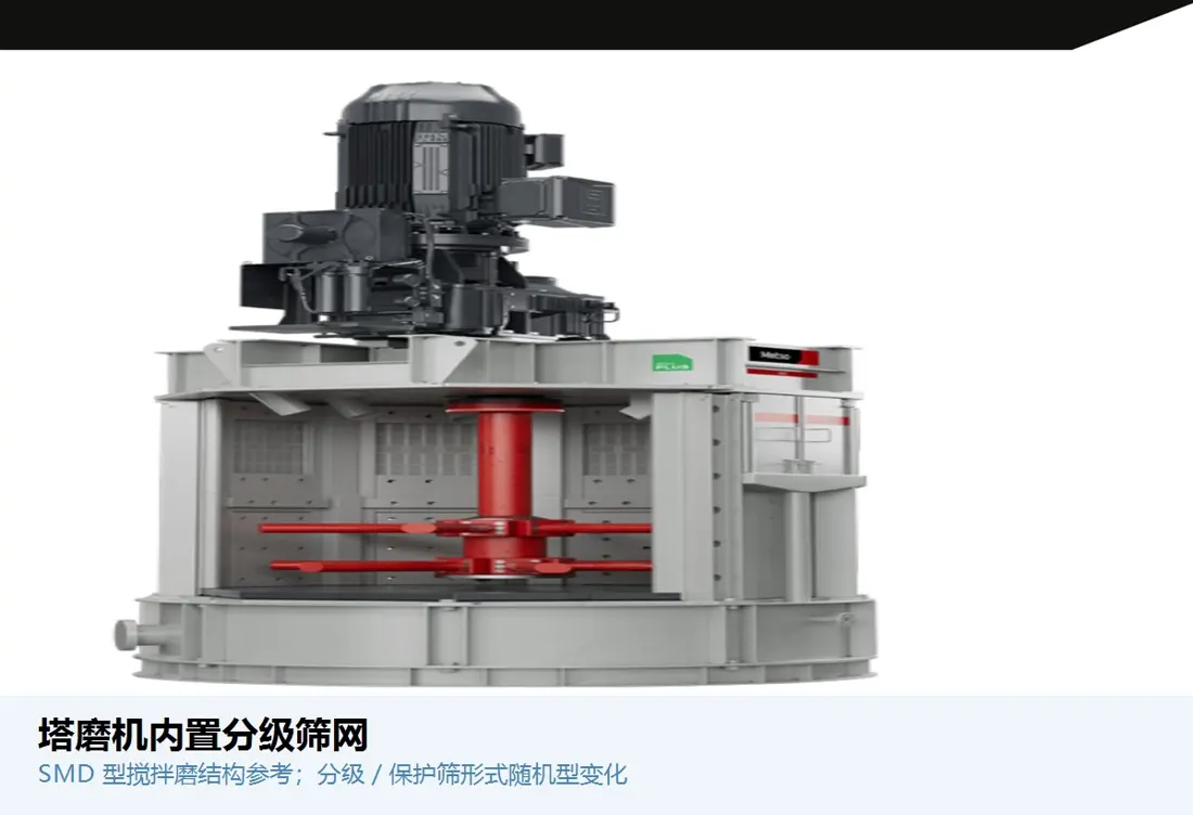
Model-specific internal arrangements Internal Screening / Classification Parts
Used only in the corresponding mill design. Confirm the OEM, full model designation, installation stage, slots, flow direction and adjacent rotors and stators.
Sealing and Support Spares
Reliability also depends on parts outside direct ore contact
Shaft seals, bearings and drive parts are maintenance spares. Inspect them separately from wear parts while coordinating both within the same shutdown plan.
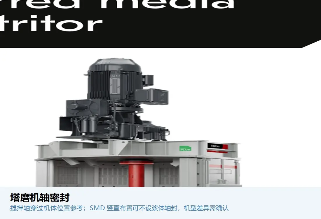 Slurry isolation
 Shaft Seal
Separates slurry, lubricant and external contaminants. Specify by shaft diameter, speed, runout, pressure, temperature, flushing and seal material.
Support assembly Bearing and Sealing System
Assess the shaft, bearings, housing, lubrication, seals and monitoring as an integrated system. Simply copying an individual seal is insufficient.
Power input Gearbox and Drive Interfaces
Confirm motor power, input and output speeds, torque, shaft ends, couplings, lubrication and mounting dimensions. External appearance alone is insufficient for selection.
Position, Performance and Material
Select materials for fine-particle abrasion, media pressure and structural support
Material families support initial selection. Confirm the actual grade, hardness, lining, bond and thickness for the mill model and operating conditions.
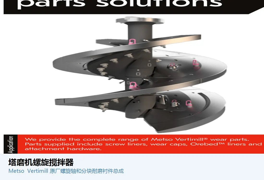
Design-specific wear parts: Metso Vertimill® replaceable wear parts include screw wear liners, end liners, shaft wear caps, shaft liners and body liners. Shaft liners may use rubber, while wear-cap designs include cast iron, rubber or polyurethane. SMD wear parts include impeller arms, end plates, body and base liners, media retention screens and mounting parts. FLS grinding consumables also include rotors and stators. Metso Stirred Mill Parts · FLS Parts & Services
Failure Diagnosis
Profile, clearance and coaxiality problems can accelerate wear
Record adjacent parts when measuring worn components. Do not attribute eccentric wear to material alone.
| Observed condition | Priority checks | Corrective approach |
|---|---|---|
| Localized uneven wear on the screw or rotor | Shaft coaxiality, mounting eccentricity, body clearances, media distribution, direction of rotation and feed position | Restore assembly datums and clearances before optimizing wear-part materials and profiles |
| Worn-through parts damage the permanent structure | Wear limits, inspection intervals, loose fastenings, adjacent wear parts and shutdown planning | Record position identifiers and remaining thickness, and replace high-risk zones as a system |
| Retention-screen blinding or grinding-media escape | Slot size, media size, differential pressure, deformation, fastening and upstream particles | Restore screen geometry and support rather than simply widening the slots |
| Shaft-seal leakage or scored shaft sleeves | Shaft runout, surface condition, seal material, flushing, slurry pressure, bearings and coaxiality | Address shaft sleeves, seals, bearings and lubrication as one system |
| Abnormal power consumption or product particle size | Wear-part profiles, clearances, media loading, speed, solids concentration, feed and classification | Assess wear alongside process data; hardness alone does not determine performance |
RFQ and Quality Control
Enquiry Requirements for Vertical Stirred Mill Wear Parts
Identify the mill design and installed revision before confirming materials, dimensions and supply scope.
Equipment identification
OEM, series, full model designation, serial number, power rating, year of manufacture and modification records.
Stirring mechanism
Screw, disc or rotor–stator design, stage count, direction of rotation, assembly number and model details.
Drawings and dimensions
Installation and part drawings, outside diameter, thickness, hole positions, interfaces, clearances and wear limits.
Grinding conditions
Media, ore, feed and product sizes, solids concentration, speed, power, throughput and temperature.
Materials and failures
Current material, lining, hardness or elasticity, service life, remaining thickness, uneven wear, cracks and photographs.
Acceptance and delivery
Materials, dimensions, non-destructive testing, lining adhesion, dynamic balance or trial assembly, identification, BOM and traceability.
Related Equipment and Parts
Related equipment, OEM series, individual wear parts and materials
Compare mill designs, identify OEM models and drawing, and review individual parts for installation positions, materials and enquiry requirements.
Tower and Vertical Stirred Mills Explore the mill structure, operating principle and general-purpose parts. Swiss Tower Mills / HIGmill Explore OEM brands, series and equipment specifications. Metso Vertimill® VTM Explore series, models, model references and application scope. Materials and Manufacturing Processes Select material families by operating conditions, failure modes and manufacturing constraints.