MMD Mineral Sizer Mineral Sizers

Officially Series and typical size confirmation installer, inlet girth gear stalk, side wear plate and shaft line gearbox, bearing and confirmed spare parts No.

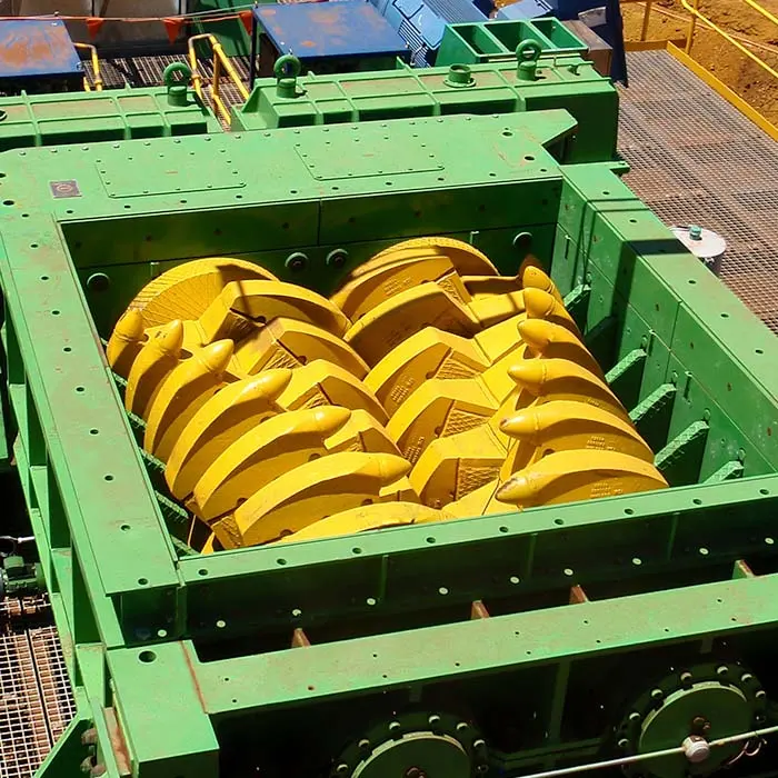
MMD Mineral Sizer Original Factory Equipment Figures
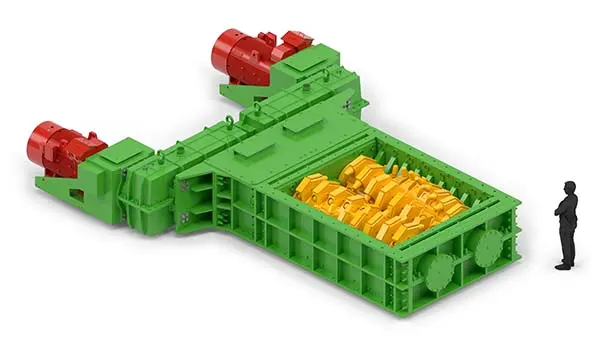
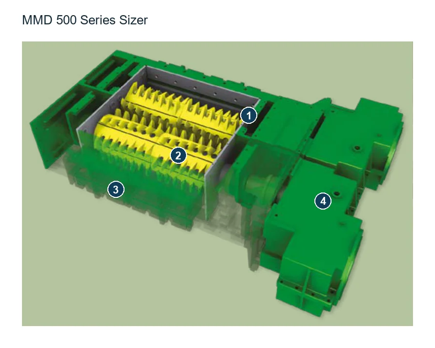
MMD Official Mineral Sizer Product diagrams for Identification Double-axis crushing chamber, tooth segment arrangement and Housing Construction.
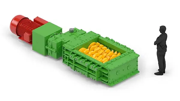
MMD 625 Series Sizer Original Factory Series Figures
MMD Official 625 Series Sizer Series Graphics; specific Tooth Profile, Length of Injection and Driver Configuration by Item OK.
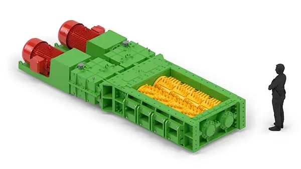
MMD 1300 Series Sizer Original Factory Series Figures
MMD Official 1300 Series Sizer Series Graphics; for large Series Forms and scale Identification.
OEM Equipment Details

Series, parts Location and spare parts The number is concentrated on the same page.

This page retains only information directly related to the wear parts, transmission spare parts and graph-based manufacturing. The teething shape of MMD Sizer'S center distance is changed by its input length as well AS drive configuration with materials or projects that require final verification using nameplate (complete model), serial number(r) layout drawing; drawings in general format).

200/350–1500 Official Sites Current Sizer Series
1980 First Piece 500 Series Sizer
2500+ Official website posted Sizer Loading capacity
14 This page has been listed traceable number
Standard Models and Key Dimensions

MMD Sizer Standard Series With typical size

Tables used below MMD Current official product page is open Series With typical scales. Dimension and weight with Tooth Profile, Length of feeds and center distance form as well. Configuration Changes.

Sizer SeriesOfficially typical heightOfficially typical width/weightKey Identification Criteria
200 / 350 Series400 mm Height of the entire machineSmall Series Other sizes by specific Configuration ConfirmationLower processing and lower granularity of discharge
500 Series615 mm High1870 mm Guang / YoY 12 ts Configuration For primary, secondary or third grades; fixed center distance tunable centre range and single rotor
625 Series770 mm High2090 mm Guang / YoY 26 tPrimary or intermediate treatment is usually used for medium-term processing Secondary Crushing
750 / 850 Series1330 mm High2400 mm Guang / YoY 40 tFor higher processing volumes, the Tooth Profile Configuration Primary or secondary
1000 Series1590 mm High3020 mm Guang / YoY 60 tThe larger center distance; often 750 Series Secondary Equipment Combination
1300 Series1845 mm High3600 mm Guang / YoY 95 tFor high processing of stripped goods and large mine materials
1500 Series2195 mm Highwidth and weight by specific Configuration ConfirmationMMD Current Open Large Sizer Series

Official website for each Series Size and weight are marked as typical values; spare parts Manufacturing The station should still be Equipment nameplate, serial number, general arrangement drawing and parts Figures are correct.

Wear Parts

smashing cavity wear parts and materials Pathways

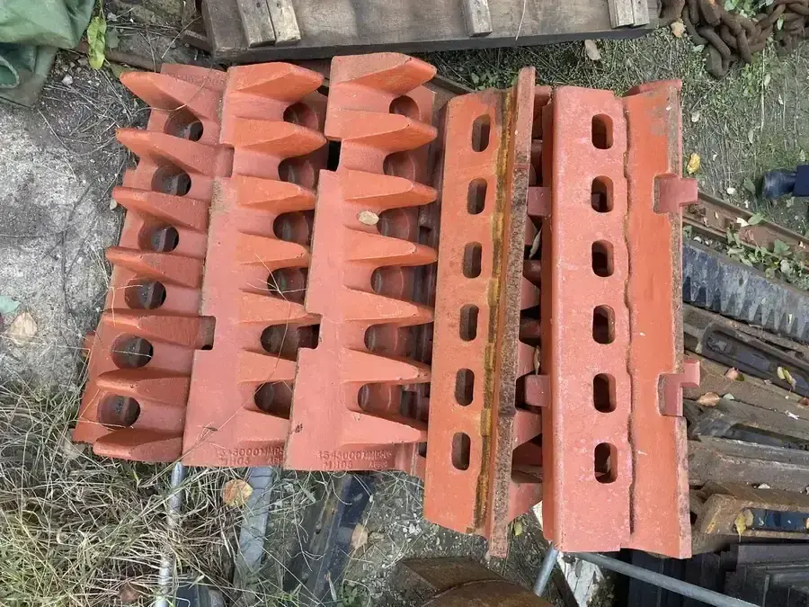
by installation position Differences girth gear Tooth section, toenails and side wearables plates; crushing beam combed with a scraper or roller shell. Card links into uniform parts Material Page.

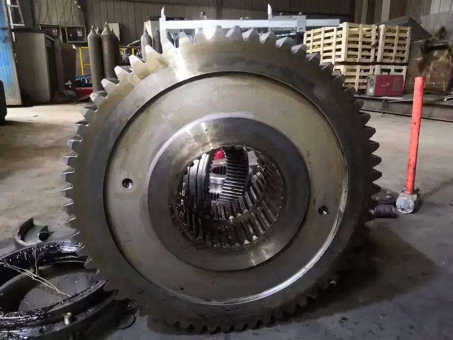
girth gear / Dental segment Identification Figures
01

girth gear / Dental segment

Tooth Ring / Tooth Segment

Mounting In the smashed shaft, Tooth Profile, the number of teeth and angles together determine bite-and -out. Series, the position of axle and angles in tooth segments.

Material Selection: Known information includes ZG30CrMnMo, Mn13Cr2 / ASTM A128 B-2;Actual Material Selection Confirm by impact, abrasion and original plot.

View Part Details →
Hats and fixed Part / Assembly Identification Figures
02

Hats and fixed Part / Assembly

Tooth Cap & Retention Assembly

Contains tooth cap and its fixed Construction; Required Checks Mounting Profiles, fixed modes and borehole systems Tooth Profile It cannot be interchangeable only by appearance.

Material Selection: Heavy tooth caps, fixed parts and substrate materials Confirms according to the original drawings, impact load and assembly requirements respectively.

View Part Details →
Side wearable and terminal plates Identification Figures
03

Side wearable and terminal plates

Side Wear Plate / End Plate

Located on the side and end of a crushing cavity, it controls material leakages. Housing Contours, holes and thicknesses Mounting Breakthrough by general arrangement drawing and the current-use items are confirmed.

Material Selection: Confirm by material abrasion, impact strength and original texture wear-resistant steel plate or casting wear parts Programmes.

View Part Details →
Broken lid and cleaning caps Identification Figures
04

Broken lid and cleaning caps

Breaker Bar Cap / Cleaning Comb

Fractured beam caps involved in final granularity control, and the cleaning is used for wet Feed Conditions Fix the root of your teeth. must be clicked on host Configuration and installation position Identification.

Material Selection: The available information will be ZG30CrMnMo Used for tooth shard and crushed beam parts; the cleaning should still be confirmed by original material.

View Part Details →
Tooth-Segment Bolts With fixed-pieces Identification Figures
05

Tooth-Segment Bolts With fixed-pieces

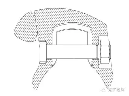
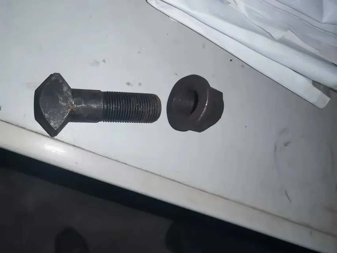
Tooth Segment Bolt & Fastener

Receives a transmutation shock, clamping and vibration load. screwed head Construction, strength level and pre-fastening requirements as well ASAPs must be checked simultaneously.

Material Selection: In the original picture alloy steel Statues, Heat Treatment Condition Mechanical properties and surface Protection Requests Manufacturing.

View Part Details →
Roller Shells / Axle Identification Figures
06

Roller Shells / Axle

Roll Shell / Drum

As a dent segment Mounting and core loads for torque transmission Construction The length of the shaft, outer diameter and tooth segment must be verified Mounting Interfaces, keys or buzzword and dynamic balance requirements.

Material Selection: Structural material, forging or casting routes and heat treatment Follow the full picture and NDT Requests for confirmation.

View Part Details →
Spare Parts

Axle, scattering and Drive spares

General Power Transmission Items are listed separately. gearbox, couplings and shaft. bearing, bearing housing and liquid force couplings must be installed on the full Interfaces Converging.

Breakdown shafts in total Identification Figures
01

Breakdown shafts in total

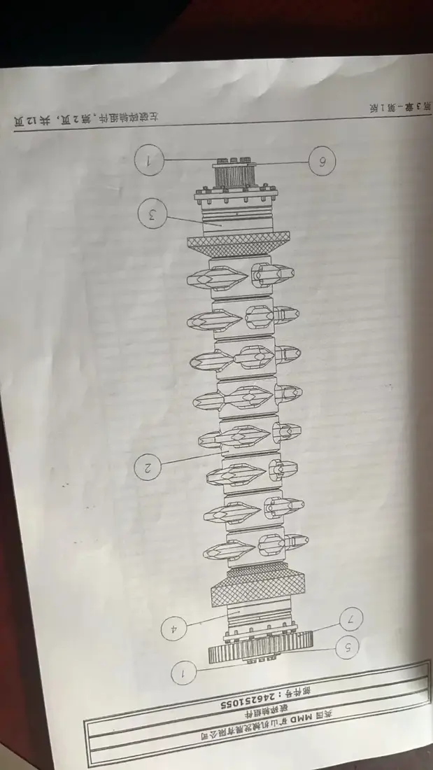
Roll Shaft Assembly

Package Main Shaft stalking segment Mounting Zones, endpoint connections and hull Interfaces It must be complete Series axis position, rotational direction general arrangement drawing and the axis diagrams are confirmed.

Material Selection: Axle axis materials, heat treatment, NDT Scale tolerances and surface Quality Confirm by the original chart and load conditions.

View Part Details →
Bearings and Bearing Housings Identification Figures
02

Bearings and Bearing Housings

Bearing & Bearing Housing

radial and axle loads of low-speed large torque shaft; bearing Looping, seat hole and seals Interfaces Must Check the Mating System.

Material Selection: bearing model s IOM and the recording of machine-installation; bearing housing Material, machining precision and NDT Performs according to the original diagram.

View Part Details →
Specialized gearbox Total cum Identification Figures
03

Specialized gearbox Total cum

Sizer Gearbox Assembly

MMD Sizer Low speed torque Power Transmission Core Assemblies; quotation Prior confirmation gearbox model, speed ratios and input endpoint Mounting Directions and Interfaces.

Material Selection: gear and the axis alloy steel, heat treatment, toothed face Accuracy and inspection Requires confirmation by original image or traceable specimen.

View Part Details →
gear Link-based devices Identification Figures
04

gear Link-based devices

Gear Coupling Assembly

Connection drives and axis, with limited compensation Mounting Deviation; stalk, incision girth gear, sealing and lube Construction Must be pressed Interfaces Dimensions Check the Mating System.

Material Selection: Dental stalk materials, heat treatment and Fit and contact accuracy Confirm by the original diagram and check for allowable torques Mounting Deviance.

View Part Details →
Liquid force coupling Identification Figures
05

Liquid force coupling

Fluid Coupling

For driving slowdown and Overload Protection. Coupling devices must be confirmed complete model, Filling requirements and input output Interfaces and Protection Configuration.

Material Selection: Total selections for nameplate, Interfaces Sizes and Power Transmission The parameters are correct, and no extraterrestrial replacement.

View Part Details →
Drawing and Spare Part Numbers

MMD 625 / 154 Recognized spare parts No

The following numbers are from local MMD IOM Handbook, customer installer files and ANRANST Production records; only for correspondence model and parts Location Identification.

Applicable ModelsPartCategory: Directory numbersEvidence Properties
MMD 625 / 154girth gear / Toothed segment, 0 °5050132-06MMD IOM + ANRANST Production records
MMD 625 / 154girth gear / Toothed segment, 15 °5050133-06MMD IOM + ANRANST Production records
MMD 625 / 154girth gear / Toothed segment, 30 °5050134-06MMD IOM + ANRANST Production records
MMD 625 / 154girth gear / Toothed segment, 45 °5050135-06MMD IOM + ANRANST Production records
MMD 625 / 154girth gear / Toothed segment, 60 °5050136-06MMD IOM + ANRANST Production records
MMD 625 / 154girth gear / Toothed segment, 75 °5050137-06MMD IOM + ANRANST Production records
MMD 625Standard-length thin housing Part / Assembly346250424MMD IOM
MMD 625Abrasion plate Part / Assembly146251943MMD IOM
MMD 625Heavy tooth cover and fixed-seats combined145060084MMD IOM
MMD 625gear Combined couplings111701004MMD IOM
MMD 625MMD R200 30: 1 gearbox Total cum146251966MMD IOM
MMD 625Rotary wagons145040240MMD IOM
MMD 154Spherical Roller Bearings23132 CC C3 W33MMD IOM
MMD 154Oil seal175×200×15R4 DIN 3760MMD IOM

Selection Guidelines: The number must be used in conjunction with the complete model, axis positioning and angles. A set of duplicate numbers is identified from a source that has been excluded by an open table without verifyation as not being published outside it

Only know MMD 625 Can I directly determine the dents?

Cannot. also confirm the position of a shaft, tooth segment angles Tooth Profile Fixing, and fixating the way serial number and Drawing Revision This page number is used to narrow the scope of check-ups.

Why 750 and 850 Put in the same Series OK?

MMD Current Official Sizer Range - General / as the same display lattice; parts Still must be complete model and Item Configuration Differences (750; 850)

materials Can you replace it only by the name?

No. The number is only a first sieve, and must be checked simultaneously parts Location, impact and abrasion operating conditions, sectional and heat treatment, Hardness gradients, NDT and the drawings requirements.

Submission MMD Sizer model, Angle Perspectives drawing number Or specimen

Provide complete model, serial number axis positioning and tooth angles drawing numbers; photo-drawal data available for use in the field of photography (photograph), drawings or materials as well. We are able thus perform identification tests with material assessments by manufacturing organizations - quality control & finished part delivery

Manufacturing Services in China

From Technical Assessment to Finished-Part Delivery

ANRANST provides customers worldwide with coordinated consulting, supplier sourcing, quality control and finished-part delivery for custom parts, wear parts and industrial spares from China, with scope to support other custom industrial parts.

01

Technical Advice

Equipment and part identification, drawing review, material selection and manufacturing feasibility assessment.

02

Supplier Introductions

Match requirements with suitable manufacturers in China and coordinate the exchange of technical information.

03

Quality Control

Drawing confirmation, material and process control, production tracking, inspection and acceptance coordination.

04

Finished-Part Delivery

Coordinate manufacturing, quality confirmation, packaging and delivery of complete finished parts.

Provide the existing model, drawings, drawing or part numbers, materials or operating conditions so we can identify the appropriate technical review and supply route.

Submit an Enquiry