
Tooth Segment / Tooth Cap
A general wear part category for center sizers. Confirm the installation position, profile, hole pattern, material and applicable model against the equipment drawings.
View General Part Details →Start with the brand, equipment series and installed machine, then explore wear parts, drive and structural spares, materials and processes, drawing review, quality control and finished-part delivery.

This page covers equipment series and models, part locations, materials and processes, drawing review and inquiry options. Before manufacture or quotation, confirm drawing, dimensions and tooling suitability against the complete model and drawings.
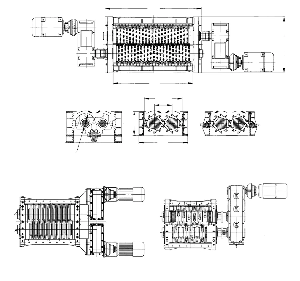
The model table assists with machine identification. Manufacture and quotation require the nameplate, complete model, serial number, drawing, general arrangement and drawing revision.
| Series / Model | Equipment Range and Identification | Equipment History and Identification |
|---|---|---|
| Center Sizer | Use the complete model, serial number, drawing and general arrangement together to identify the installed equipment | Identify the installed machine from its equipment records |
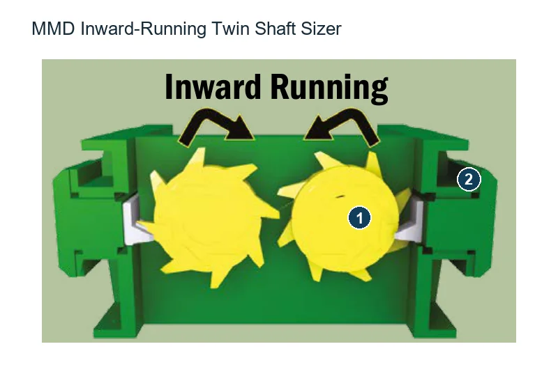
The numbers on the diagram correspond one to one with the rows below.

| No. | Component | Location | Applies to |
|---|---|---|---|
| 1 | Sizer rotor assemblies | Two inward-running rotors in the centre of the section | MMD twin-shaft Sizer inward-rotation configuration (no separately named series) |
| 2 | Main frame | Supporting frame around the two rotors | MMD twin-shaft Sizer inward-rotation configuration (no separately named series) |
These general Center Sizer part categories help identify the part you need. Confirm suitability against the specific MMD model and drawings.
Tooth Segment / Tooth Cap
A general wear part category for center sizers. Confirm the installation position, profile, hole pattern, material and applicable model against the equipment drawings.
View General Part Details →Tooth Segment Bolt
A general wear part category for center sizers. Confirm the installation position, profile, hole pattern, material and applicable model against the equipment drawings.
View General Part Details →Side Liner / End Plate
A general wear part category for center sizers. Confirm the installation position, profile, hole pattern, material and applicable model against the equipment drawings.
View General Part Details →Bottom Liner / Base Plate
A general wear part category for center sizers. Confirm the installation position, profile, hole pattern, material and applicable model against the equipment drawings.
View General Part Details →Scraper / Cleaner
A general wear part category for center sizers. Confirm the installation position, profile, hole pattern, material and applicable model against the equipment drawings.
View General Part Details →Identify gears, shafts, sleeves, bearings, seals, hydraulic parts, supports and connectors for drawing review. Listed OEM drawing or part references relate to identified parts and require confirmation against your machine.
Roll Shaft
A general structural or drive part category for Center Sizer. Confirm interfaces, accuracy, material and applicable model against the equipment drawings.
View General Part Details →Gearbox / Drive
A general structural or drive part category for Center Sizer. Confirm interfaces, accuracy, material and applicable model against the equipment drawings.
View General Part Details →Bearing / Bearing Housing
A general structural or drive part category for Center Sizer. Confirm interfaces, accuracy, material and applicable model against the equipment drawings.
View General Part Details →Hydraulic Coupling
A general structural or drive part category for Center Sizer. Confirm interfaces, accuracy, material and applicable model against the equipment drawings.
View General Part Details →Provide the complete model, serial number, drawing revision, installation position, photographs of the current part, material and operating conditions.
No. General images help identify the part category. Manufacture requires agreed drawings, dimensions, interfaces, materials and acceptance criteria.
Start with the nameplate, general arrangement drawing, installation position, used-part photographs and key dimensions. We can then assess the feasibility of dimensional inspection, material evaluation and manufacture to drawing.
Provide the complete model, serial number, nameplate, installation position, photographs of the current part, drawings, material and operating conditions. We use these to identify the part, assess materials, organize production at certified foundries, coordinate quality control and arrange finished-part delivery.
Or contact us directly: +86 156 3797 3199
zzx@anranst.com
ANRANST provides customers worldwide with engineering assessment, production at certified foundries to the customer technical requirements, quality control and finished-part delivery for custom wear parts and industrial spares, with scope to support other custom industrial parts.
We review mating surfaces and interface dimensions and assess material, heat treatment and manufacturing feasibility.
Material grades and heat-treatment processes are specified order by order, stated in the technical agreement and tracked through production.
Drawing confirmation, material and process control, production tracking, inspection and acceptance coordination.
We coordinate manufacturing, quality confirmation, packaging and delivery of complete finished parts in a workable, closed-loop supply process.
Provide the existing model, drawings, drawing, materials or operating conditions so we can identify the appropriate technical review and supply route.
Submit an Enquiry