MMD Apron Plate Feeder Apron Feeders

D4 / D7 / D10 / D11 — / / / — s D, D, D, D Type and core width confirmation installer, inlet apron pans, Impact Liners, chaines and sprocket, support roller and tightness spare parts (;;; )

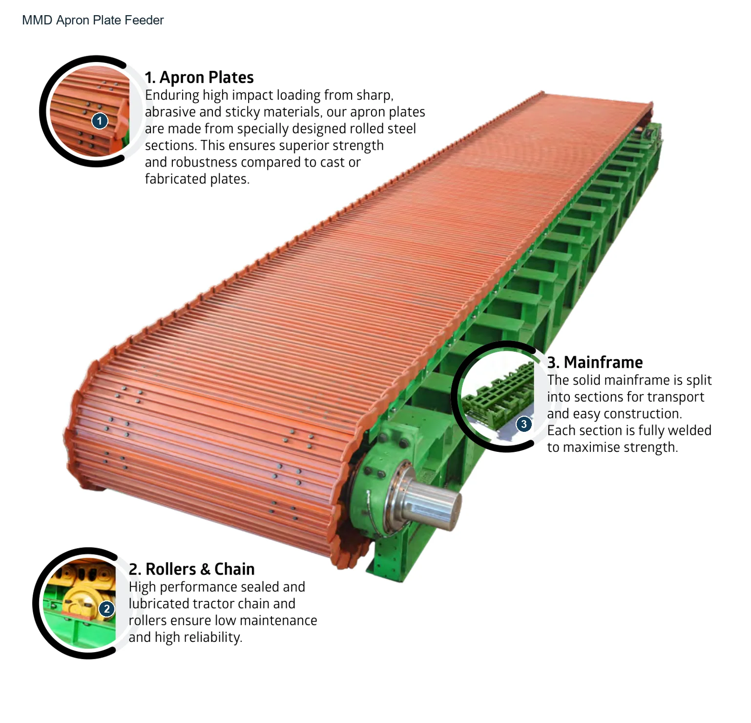
MMD Apron Plate Feeder Original factory plot
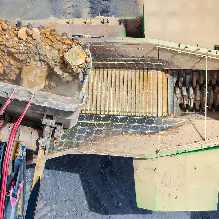
MMD Official Heavy-duty Apron Feeders Field maps for Identification Direct unloading, feed area and downstream Sizer The splintering.
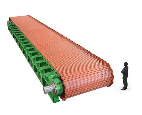
MMD D10 Apron Plate Feeder Original Factory Series Figures
MMD Official D10 Type Feeding machine Series Pictures.
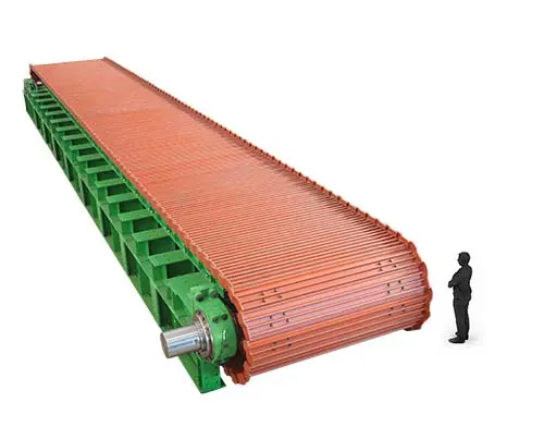
MMD D11 Apron Plate Feeder Original Factory Series Figures
MMD Official D11 Type Feeding machine Series Graphs; Length by Material and Item Demand Custom.
OEM Equipment Details

D Types of Series, Key dimensions and wear parts concentrating Identification

The MMD board feeder is used to withstand large bulk materials directly unloading and stabilize the feeding downstream.The page retains only information that relates directly with wear parts, chain transmission or graphics manufacturing; specific length of material processing volume as well AS drive configuration are determined by project.

D4–D11 The four types of the official website
1500–4000 mm Effective official width range
1989 The first year of the smelting machine
150+ Official website posted Global Loading capacity
Standard Models and Key Dimensions

MMD D4, D7, D10, D11 Key dimensions

The following table uses the MMD official plate feeder product pages for open data, width and height are used in install start-ups with lengths as well to final configuration according material processing volume / density or project requirements.

TypesWhole machine widthHeight of the entire machineEffectively conveying width
D4 Type2160 mm1200 mm1500 mm
D7 Type2775 mm1480 mm2000 mm
D10 Type3990 mm1960 mm3000 mm
D11 Type5025 mm2260 mm4000 mm

Manufacturing apron pans, chain and Power Transmission Before the item, checks must be made. complete model, serial number, Chain distances and effective width general arrangement drawing, Parts Maps and Drawing Revision.

Wear Parts

Feeding and conveyor areas wear parts

s apron pans Feeding Zone impact plates, side liners.Headtail Liners and backpacking installation position Distinguish and connect to the unified parts Material Page.

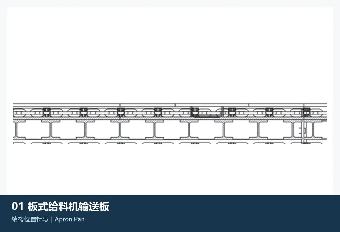
Apron Pan / Feeder Pan Identification Figures
01

Apron Pan / Feeder Pan

Apron Pan / Feeder Plate

The continuous load of large blocks and forming a conveyor surface.The plate width, sectional surfaces; the connection hole to connect with each other D Types of Series Confirmation with the drawings.

Material Selection: MMD Official description of the use by heavy-duty rolling plate Construction. substrates, welding and wear-resistant layers heat treatment Graphics and Impacts operating conditions Confirmation.

View Part Details →
Category: Subsistential areas impact plates Identification Figures
02

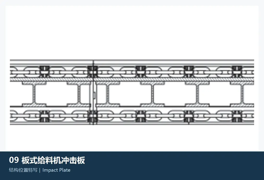
Category: Subsistential areas impact plates

Impact Plate

Location in the area of direct discharge and shock attenuation, protects subjects Construction and dispersion of large blocks material impact; the outline, thicknesses or fixed manner must be according to installation position Confirmation.

Material Selection: Echo Impact Toughness, plastic resistance deformation and replaceability as cores of the brand name & composite Construction by operating conditions and the original graph confirmed.

View Part Details →
side liners / Layout side Liners Identification Figures
03

side liners / Layout side Liners

Side Liner / Skirt Liner

Control the material spill over along both sides of a conveyor channel and protect side walls. Mounting Confucius, pluggings and gaping apron pans The motor relationship must be reconciled simultaneously.

Material Selection: Select according to sliding abrasive, block bearing and thickness limit wear-resistant steel plate Or replaceable casting Liners.

View Part Details →
Head-End Discharge Chute Liner Identification Figures
04

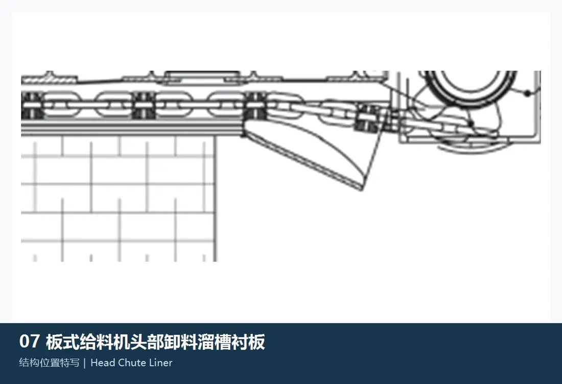
Head-End Discharge Chute Liner

Head Discharge Chute Liner

In the head of discharging and material turning area, withstands shocking rustling. The traceability must be confirmed Liners partitioning, connection mode and replacement space.

Material Selection: Select by impact and sliding abrasive ratio wear-resistant steel plate, Composite liners or localized reinforcement programs.

View Part Details →
Tail-End Inlet Liner Identification Figures
05

Tail-End Inlet Liner

Tail Inlet Liner

Protecting the tail feed and fallout boundaries Construction. Combination of fallout, blockage level and material flow to the adjacent apron pans Recognize the operating gap.

Material Selection: materials and thickness by impact, abrasionability. Construction The combination of sling and replacement cycles.

View Part Details →
Re-entry trailer Liners Identification Figures
06

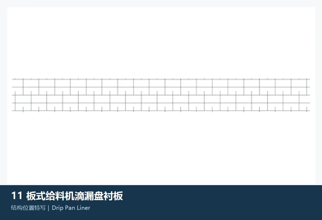
Re-entry trailer Liners

Drip Pan Liner

Collecting the paste and protecting bottom. Construction Shape, splicing and discharge direction as well the cleaning space is confirmed by a full machine arrangement.

Material Selection: Usually, the main focus is sliding abrasion and maintenance resistance. Material Selection Graphs, materials and service life Requests for confirmation.

View Part Details →
Spare Parts

Links, sprocket, support roller With tightness spare parts

General Power Transmission The slate is listed separately; the chain spacing, pins bushings Co-operation, sprocket Tooth Profile and support roller bearing Must be the same one. Equipment Check the Mating System.

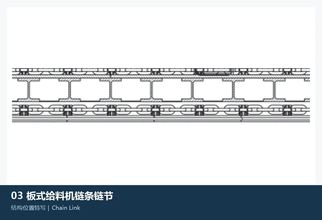
Chain Link Identification Figures
01

Chain Link

Chain Link

As the core loader of a traction chain carries continuous pull and impact payload. The spacing, pore lengths are thick heat treatment and Packing Matching Requirements Required Checks.

Material Selection: Links Piece materials, forging or casting routes; heat treatment and NDT Performs according to the original diagram and design load.

View Part Details →
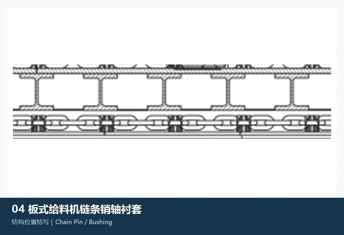
chain pins and bushings Identification Figures
02

chain pins and bushings

Chain Pin & Bushing

Forming a chain swirl and bear contact fatigue Abrasion and shock. pins Diameter, bushings Wall thickness, co-operations and lubrication of surfaces Check the Mating System.

Material Selection: s alloy steel, surface hardening and core toughness are the main control points. The actual parameters confirmed by drawing

View Part Details →
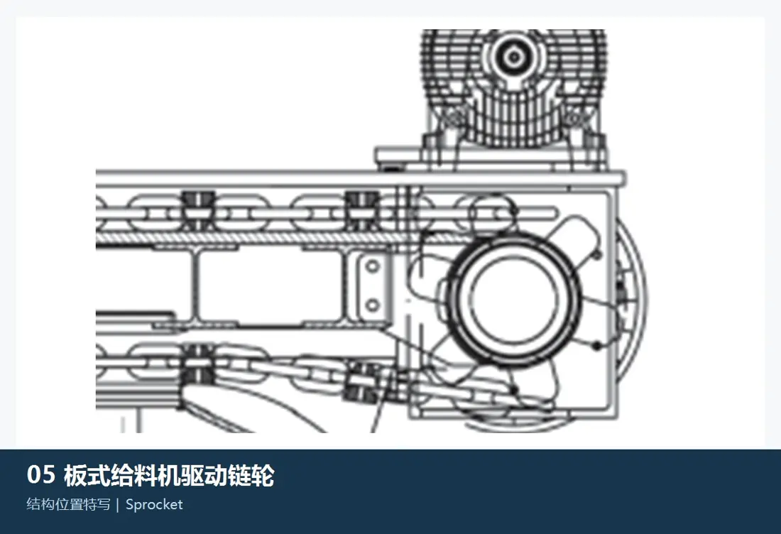
Drive Sprocket Identification Figures
03

Drive Sprocket

Drive Sprocket

Links with the traction chain to pass through drive torque. Tooth Profile, spacings and number of teeth. Interfaces and Mounting The direction must be confirmed with the chain and axle.

Material Selection: The strength of the tooth surface, wear-resistant layer and core toughness. Tooth Profile Accuracy and NDT by Power Transmission Requests for confirmation.

View Part Details →
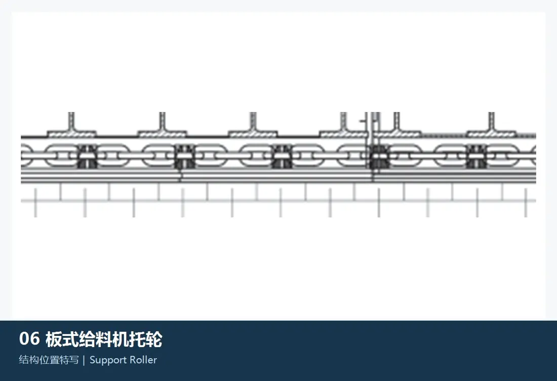
support roller / Bearing Roller Identification Figures
04

support roller / Bearing Roller

Support Roller

In the run of scaffolding apron pans and traction chains, affecting the operation resistance to a chain positioning system as well smoothness of its plate. bearing and sealing should be coated Identification.

Material Selection: Wheels, shaft and bearing and seals on the load, Speed Confidentialization of pollution and the conditions for lube.

View Part Details →
Links tensioning system Identification Figures
05

Links tensioning system

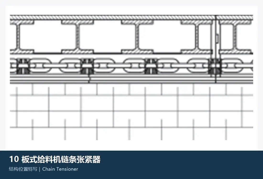
Chain Tensioner

The compensation chain extends and maintains a reasonable tension. Tension, force direction / hydraulic or mechanical Interfaces and lockdown Construction It must be confirmed by the whole machine.

Material Selection: Construction parts, shafts and bushings The seal and the sealed separately confirm by loads as well in tightness.

View Part Details →

Only know D10 Can I be directly determined apron pans ?

Cannot. It is also necessary to confirm the effective width, length of machine frame and chain distances; plate type or fixed hole serial number and Drawing Revision.

Links, sprocket and pins Can we be mapped separately?

Can be separate Manufacturing but technical confirmation It should be stained to avoid the spacing, Tooth Profile The sequencing and the running trajectory are inconsistent.

Why not be public MMD part number ?

Retracing data is not currently reliable enough D4, D7, D10, D11 part number Reciprocating tables; the website does not write unverified numbers as confirming data.

Submission MMD Types of feeder, effective width drawing number Or specimen

Provide Type D type, serial number and effective widths. Chain distance; Part positioning of parts or drawings/fogurines material & operating conditions to complete identification with manufacturing organization as well quality control for finished-part delivery

Manufacturing Services in China

From Technical Assessment to Finished-Part Delivery

ANRANST provides customers worldwide with coordinated consulting, supplier sourcing, quality control and finished-part delivery for custom parts, wear parts and industrial spares from China, with scope to support other custom industrial parts.

01

Technical Advice

Equipment and part identification, drawing review, material selection and manufacturing feasibility assessment.

02

Supplier Introductions

Match requirements with suitable manufacturers in China and coordinate the exchange of technical information.

03

Quality Control

Drawing confirmation, material and process control, production tracking, inspection and acceptance coordination.

04

Finished-Part Delivery

Coordinate manufacturing, quality confirmation, packaging and delivery of complete finished parts.

Provide the existing model, drawings, drawing or part numbers, materials or operating conditions so we can identify the appropriate technical review and supply route.

Submit an Enquiry