
01
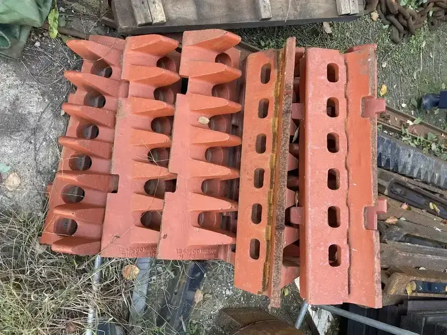
حلقات / شرائح الأسنان
حلقة مسننة / قطاع مسنن
يتم تركيبها حول عمود التكسير، ويحدد شكلها وعدد الأسنان والزاوية والترتيب التقاط المواد وتفريغها. طابق السلسلة وموضع العمود وزاوية القطعة والرسم الأصلي.
عرض دليل المكونات →حدد عملية التثبيت حسب سلسلة الشركة المصنعة والأبعاد النموذجية، ثم طابق حلقات الأسنان والقطاعات وألواح التآكل الجانبية والأعمدة وعلب التروس والمحامل ومراجع قطع الغيار الموثقة.
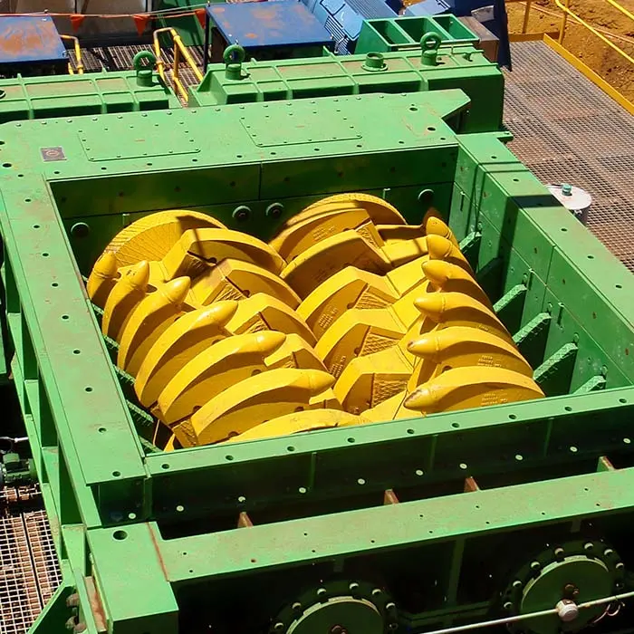
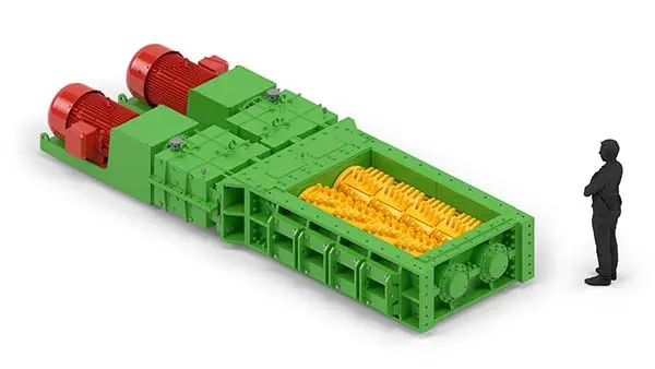
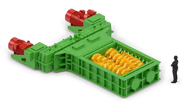
يغطي هذا الدليل أجزاء التآكل وقطع غيار الإدارة والتصنيع وفق الرسومات. تختلف أشكال أسنان سايزر MMD والمسافات بين المحاور وأطوال المداخل وأنظمة الإدارة بحسب المادة والمشروع. قبل التصنيع، طابق لوحة البيانات والطراز الكامل والرقم التسلسلي ورسم الترتيب العام وإصدار الرسم.
يتبع الجدول سلسلة MMD المنشورة حاليا والأبعاد النموذجية. تختلف الأبعاد والوزن حسب شكل السن وطول المدخل وترتيب المسافة المركزية وتكوين الإدارة.
| سلسلة الحجم | الارتفاع النموذجي للشركة المصنعة | العرض/الوزن النموذجي للشركة المصنعة | ملاحظات التحديد والتطبيق |
|---|---|---|---|
| سلسلتان 200 / 350 | الارتفاع الكلي 400 mm | سلسلة صغيرة طابق الأبعاد الأخرى للتكوين | انخفاض الإنتاجية وحجم المنتج الأصغر |
| سلسلة 500 | الارتفاع 615 mm | العرض 1870 mm / تقريبا 12 t | التكوينات الأولية والثانوية والثالثية؛ مراكز ثابتة، مراكز قابلة للتعديل أو دوار واحد |
| سلسلة 625 | الارتفاع 770 mm | العرض 2090 mm / تقريبا 26 t | عادة ما يتم التكسير الأولي أو الثانوي بإنتاجية متوسطة |
| سلسلتان 750 / 850 | الارتفاع 1330 mm | العرض 2400 mm / تقريبا 40 t | إنتاجية أعلى؛ واجب أساسي أو ثانوي حسب تكوين الأسنان |
| سلسلة 1000 | الارتفاع 1590 mm | العرض 3020 mm / تقريبا 60 t | مسافة مركزية أكبر؛ غالبا ما يتم دمجها مع آلة ثانوية من سلسلة 750 |
| سلسلة 1300 | الارتفاع 1845 mm | العرض 3600 mm / تقريبا 95 t | مواد تعدين عالية الإنتاجية ومواد تعدين واسعة النطاق |
| سلسلة 1500 | الارتفاع 2195 mm | طابق العرض والوزن للتكوين | سلسلة سايزر كبيرة مدرجة حاليا لدى MMD |
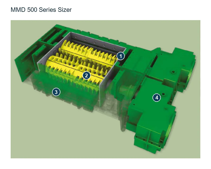
تتطابق الأرقام على المخطط مع الصفوف أدناه.
| الرقم | المكوّن | الموضع | ينطبق على |
|---|---|---|---|
| 1 | مجموعات دوارات السايزر | دواران مسننان داخل حجرة التكسير العلوية | 500 Series - التكوين المعروض من OEM |
| 2 | أسنان التكسير | الأسنان الصفراء حول دوارات السايزر | 500 Series - التكوين المعروض من OEM |
| 3 | الهيكل الرئيسي | هيكل الدعم الأخضر حول الدوارات | 500 Series - التكوين المعروض من OEM |
| 4 | مجموعة نظام الإدارة | غلاف الإدارة الأخضر عند طرف الدوار على اليمين | 500 Series - التكوين المعروض من OEM |
حدد حلقات وقطاعات الأسنان، وأغطية الأسنان، وألواح التآكل الجانبية، وقضبان الكسارة، وأمشاط التنظيف، والمثبتات، وأغلفة الأسطوانة حسب الموضع. ترتبط البطاقات بأدلة المكونات والمواد.
حلقة مسننة / قطاع مسنن
يتم تركيبها حول عمود التكسير، ويحدد شكلها وعدد الأسنان والزاوية والترتيب التقاط المواد وتفريغها. طابق السلسلة وموضع العمود وزاوية القطعة والرسم الأصلي.
عرض دليل المكونات →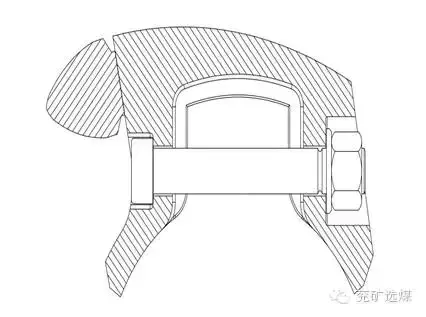
غطاء السن & مجموعة التثبيت
يشمل أغطية الأسنان وهياكل التثبيت بها. طابق قسم التثبيت، وطريقة التثبيت، وتوزيع الثقوب، وملف الأسنان؛ المظهر وحده لا يثبت قابلية التبادل.
عرض دليل المكونات →لوحة ارتداء جانبية / لوحة نهاية
تقع على جوانب الغرفة ونهاياتها لاحتواء المواد وحماية المبيت. طابق الشكل وتوزيع الثقوب والسمك وخلوص التثبيت مقابل الترتيب العام والأجزاء المثبتة.
عرض دليل المكونات →غطاء عارضة التكسير / مشط التنظيف
تساعد أغطية عارضة التكسير في ضبط حجم المنتج النهائي؛ وتزيل أمشاط التنظيف المواد الرطبة اللزجة من قواعد الأسنان. حدد كل جزء بحسب تكوين الآلة وموضع التركيب.
عرض دليل المكونات →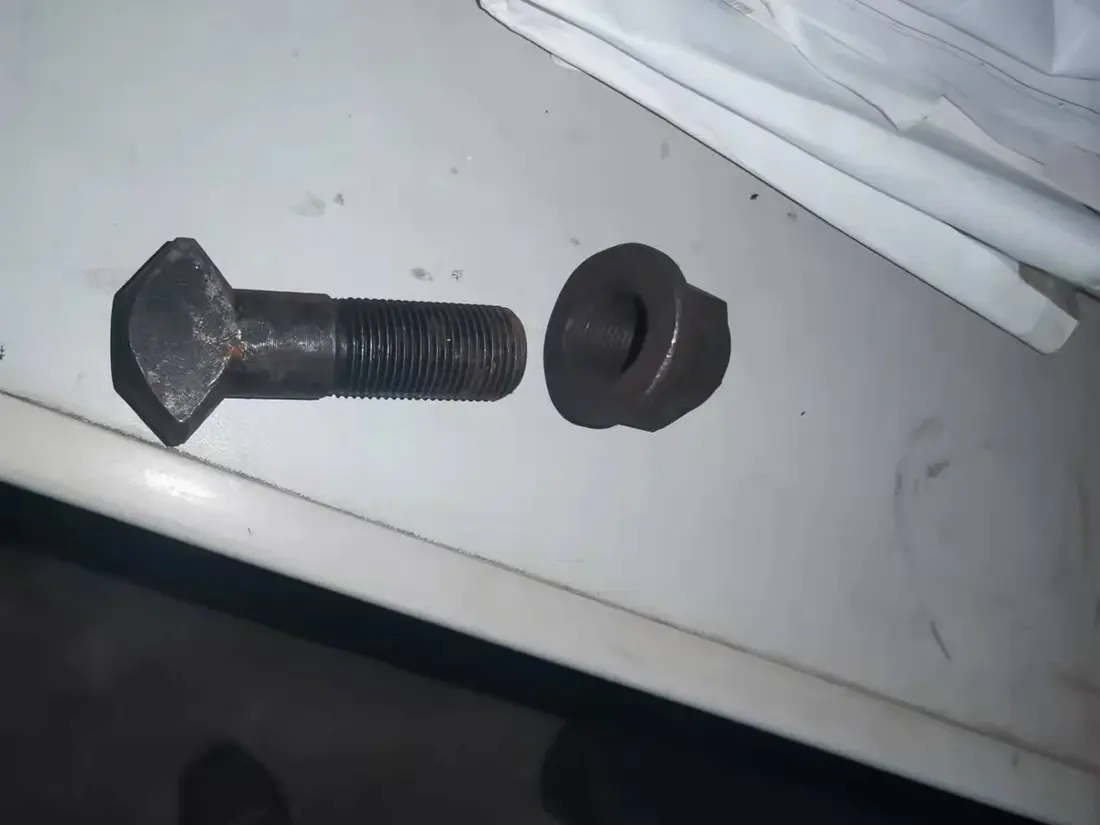
قطعة الأسنان المسمار الملولب & السحابة
تحمل تأثير متناوب، لقط وأحمال الاهتزاز. طابق اللوالب وتصميم الرأس وفئة القوة والتحميل المسبق والغسالات المطابقة معا.
عرض دليل المكونات →غلاف الأسطوانة / أسطوانة (طنبور)
تحمل هذه الهياكل شرائح الأسنان وتنقل العزم. طابق الطول المحوري والقطر الخارجي ووصلات الشرائح والمفاتيح أو الأسنان المحورية ومتطلبات الاتزان الديناميكي.
عرض دليل المكونات →يتم سرد قطع غيار الإدارة بشكل منفصل. طابق علب التروس والوصلات والأعمدة والمحامل والمبيتات ووصلات السوائل مقابل الواجهات المثبتة بالكامل.
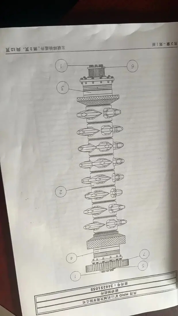
مجموعة عمود الأسطوانة
يشتمل على العمود الرئيسي ومنطقة تركيب قطعة الأسنان والوصلات الطرفية وواجهات الدعم. طابق السلسلة الكاملة وموضع العمود واتجاه الدوران والترتيب العام ورسم نظام العمود.
عرض دليل المكونات →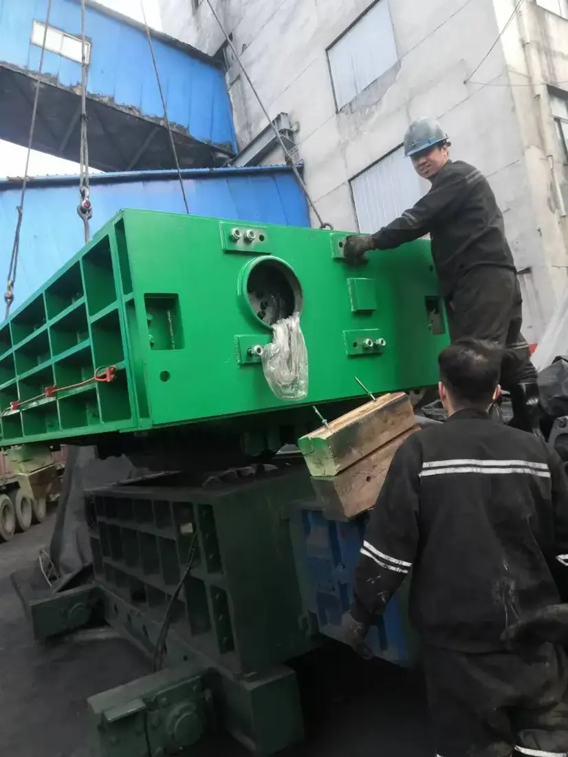
محمل & مبيت المحمل
تحمل الأحمال الشعاعية والمحورية في نظام العمود منخفض السرعة وعزم الدوران العالي. طابق خلوص المحمل، وتجويف المبيت، وموانع التسرب، ووصلات التشحيم كتجميع كامل.
عرض دليل المكونات →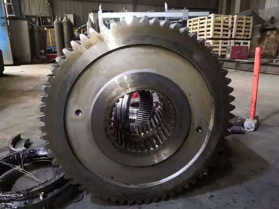
مجموعة علبة تروس السايزر
مجموعة أساسية في إدارة سايزر MMD منخفضة السرعة وعالية العزم. قبل عرض السعر، طابق طراز علبة التروس ونسبة التخفيض ونهايات الدخول والخروج واتجاه التركيب والوصلات.
عرض دليل المكونات →مجموعة القارنة المسننة
تربط الإدارة بمنظومة الأعمدة وتستوعب قدرا محدودا من عدم المحاذاة أثناء التركيب. طابق الصرات ذات الأسنان الخارجية والأكمام ذات الأسنان الداخلية وموانع التسرب وترتيبات التشحيم مع أبعاد الوصلات.
عرض دليل المكونات →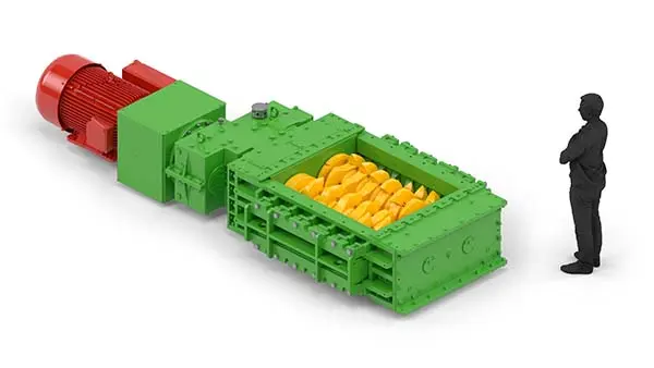
قارنة هيدروديناميكية
توفر بدءا سلسا وحماية من الحمل الزائد. طابق الطراز الكامل للوصلة ومتطلبات تعبئة السائل ووصلات الدخول والخروج وتكوين الحماية.
عرض دليل المكونات →لا. طابق موضع العمود وزاوية القطعة وترتيب الأسنان وطريقة التثبيت والرقم التسلسلي ومراجعة الرسم. المراجع هنا تساعد على تضييق نطاق البحث.
يقدم نطاق الحجم الحالي MMD 750 / 850 معا. تمييز الأجزاء الفعلية عن طريق الطراز الكامل وتكوين المشروع.
لا، فالدرجة هي مجرد مرشح أولي. طابق أيضا موضع الجزء وظروف التأثير والتآكل وحجم القسم والمعالجة الحرارية وتدرج الصلابة واكتشاف العيوب ومتطلبات الرسم.
قم بتوفير الطراز الكامل والرقم التسلسلي وموضع العمود وزاوية القطعة والرسم والصور الفوتوغرافية للأجزاء المثبتة والرسومات والمواد وظروف التشغيل. وهي تدعم تحديد المعدات وتقييم المواد وتنسيق التصنيع ومراقبة الجودة وتسليم الأجزاء النهائية.
أو تواصل معنا مباشرة: +86 156 3797 3199
zzx@anranst.com
تقدّم ANRANST لعملائها حول العالم التقييم الهندسي والإنتاج في مسابك معتمدة وفق المتطلبات الفنية للعميل ومراقبة الجودة وتسليم القطع الجاهزة لقطع التآكل المخصّصة وقطع الغيار الصناعية، مع إمكانية دعم قطع صناعية مخصّصة أخرى.
نراجع أسطح التزاوج وأبعاد الوصلات، ونقيّم إمكانية التصنيع من حيث المادة والمعالجة الحرارية.
Material grades and heat-treatment processes are specified order by order, stated in the technical agreement and tracked through production.
تأكيد الرسم، ومراقبة المواد والعمليات، ومتابعة الإنتاج، والفحص، وتنسيق القبول.
ننسّق التصنيع وتأكيد الجودة والتغليف والتسليم للقطع الكاملة ضمن سلسلة توريد متكاملة وعملية.
زوّدنا بالطراز الحالي والرسومات والمواد أو ظروف التشغيل لنتمكن من تحديد المراجعة الفنية ومسار التوريد المناسبين.
أرسل استفساراً