Epiroc DM, Pit Viper and SmartROC Surface Drill Rigs: Models and Spare Parts

Around the rotary tooth wheel, DTH and COPROD drilling systems are built a complete identification path from standard configuration numbers (Aperture diameter) deep into drill pillars; reverse propulsion system - compressed airs.

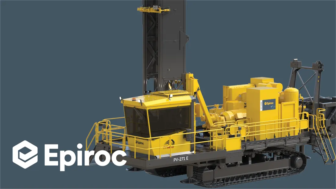
Epiroc Pit Viper 271 E Official full-length diagram
Epiroc Official Pit Viper 271 E Graphics; for use Identification The masts, drill columns and backs of the large rotary detonating hole drilling machine are turned on to be used as chassis.
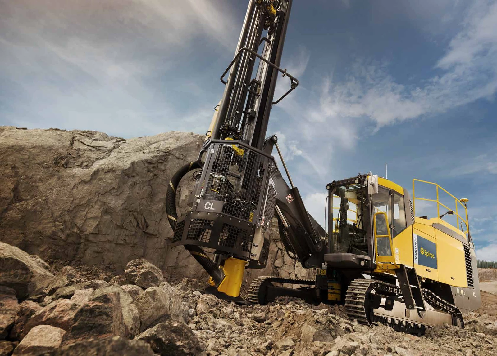
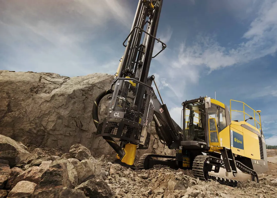
Epiroc SmartROC CL Official Mining Map
Epiroc Official SmartROC CL Graphics of work; Model Utilization COPROD Method, cannot be with Pit Viper The rotary drill column is directly mixed.
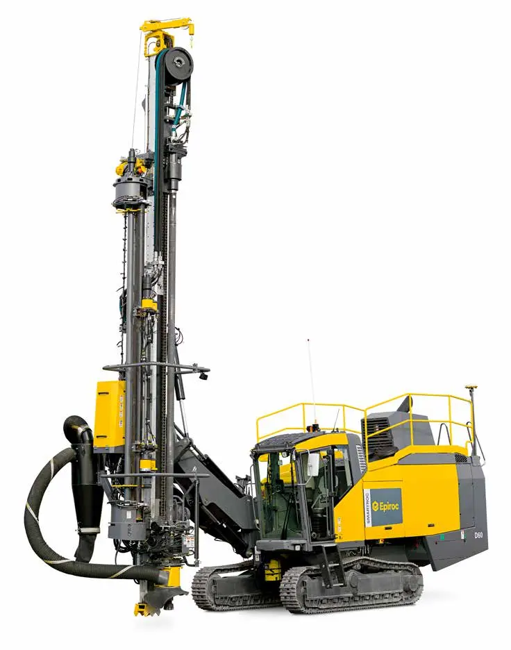
Epiroc SmartROC D60 Official full-length diagram
Epiroc Official SmartROC D60 Graphics; for use Identification DTH drilling, propulsion and masts; dust removal area.
OEM Equipment Details

First scavenging the rotation Roller cones, DTH or COPROD Re-checking model and total

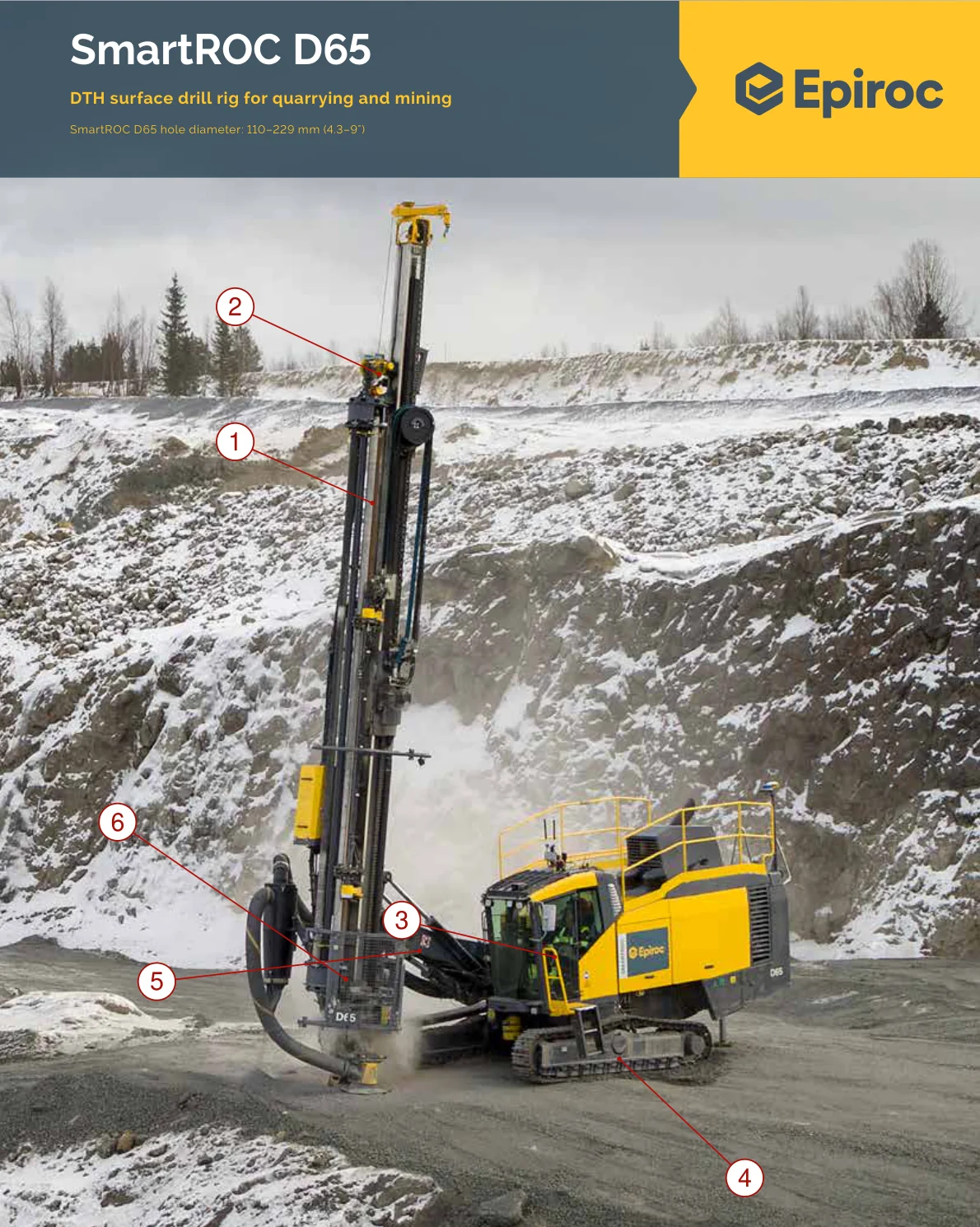
Epiroc currently covers both Drill Master, Pit Viper and SmartROC. Different series of aberrations are varied in the range: drill method; masts (rig), drilling columns - turning heads to propellant or compressed air configuration). This page serves as an identification for wear parts & core spare pieces without treating it directly interchangeable with same-aparthee equipment nor branding devices

14 Core Series variant group
110–406 mm This page opens the scope of an aperture
3 Rotating / DTH / COPROD Pathways
12 Wear Parts and Key Spare Part Categories
Standard Models and Key Dimensions

DM, Pit Viper and SmartROC Core Standard Models and Dimensions

The model and parameters are derived from Epiroc's current product catalogue, as well a single-model page. Electric drives (XC), mast polees - drilling roders; compressor & automated configuration can change the interface of equipment that cannot be replaced by only basic models for parts to replace them with other parts in an instantaneous fashion or even if they do not have any replacement on their own devices.

Standard Series / Modeldrilling pier MethodOfficial Site Open ApertureOpens the core depth of your website
DM45 / DM50Rotary Roller cones or DTH, Multi-Spin140–225 mmOne-way 8.4 m; the maximum 53.3 m
DMLRotary Roller cones or DTH, Multi-Spin149–250 mm9.1 m Shifting rod Configuration Max 53.3 m Optionary; Alternatives 10.7 m Shifting rod Configuration Max 62.5 m
Smart DMLRotary Roller cones or DTH, Multi-Spin150–270 mmOfficial Site Technology Table: Single-track 8.4 m; the maximum 53.3 m
DM75Rotary Roller cones, Multi-Spin229–270 mmOne-way 8.4 m; the maximum 51.2 m
Pit Viper 231Rotary Roller cones -way, single152–251 mmOne-way 16.1 m
Pit Viper 235Rotary Roller cones or DTH -way, single171–270 mmOne-way 12 m
Pit Viper 271 / 271 XCRotary Roller cones or DTH -way, single171–270 mmOne-way 18 m
Pit Viper 275 / 275 XCRotary Roller cones or DTH, Multi-Spin171–270 mmMax 59.4 m
Pit Viper 276Rotary Roller cones229–270 mmDeep by mast, drill pole and specific Configuration Confirmation
Pit Viper 291Rotary Roller cones -way, singleGrand aperture SeriesSize by specific diesel Model Recognizing the information
Pit Viper 351Rotary Roller cones -way, single270–406 mmOne-way 19.8 m; the maximum 41.1 m
Pit Viper Electric drive Series231 E, 235 E, 271 E, 271 XC E, 275 E, 275 XC E, 291 Eper cent model Recognizing; E the – mm, E the – mm (271; 171; 270; 291; 279; 311)271 E and 291 E One-way 18 m; other variants by single model Recognizing the information
SmartROC CLCOPROD115–216 mmMax 42.5 m
SmartROC D60DTH110–178 mmMax 56 m

RFQ provides at least complete model, serial number rig method and aperture diameters; mast/drill configuration. Turnover or aggregate numbers: OEM-Thirds Number (OEM) Nomenclature), drawings of used parts as well key dimensions. The series in which the website is available does not coincide with singlemodel pages based on one models technical data versus nameplate matching.

Wear Parts

scattering, drilling and COPROD / DTH drilling rigs and drilled in wear-resistant areas

Priority is given to the official rigs and drill images of Epiroc.The material links are an ANRANST replacement engineering screening path, not declared as a unified original brand for all models in EiroC; they will be confirmed by drawings or samples from their origin detection (see rock), borehole profile() patterns with failure methods).

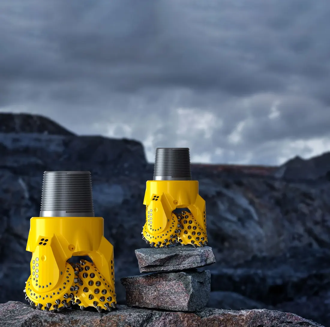
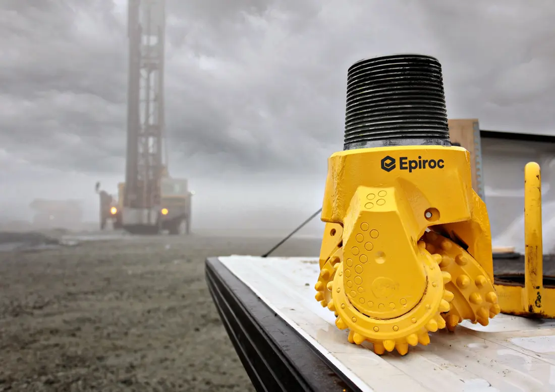
Epiroc Official rotation Roller cones Pictures of burrowing products
01

Rotary Roller cones screed drill

Rotary Tricone Drill Bits

Installed at the bottom of a rotating drilling column, directly crushing rocks. The drills must be matchable by an Aperture diameter and IADC cutting structure; steel or cementated carbide teeth to open lid bearing with seal-bearing gear: loop mode (or thread) as well in rock strength - not only according model for grinding machines

Material Selection: Cutting tools and toothpicking are evaluated from the Tungsten carbidecemented carbide system, with teeth wheels of abrasive instruments confirmed by high tough alloy steel surface reinforcement requirements.

Entering the drill and cutting tools Unified Pages
Epiroc Official Roller cones screed drill Construction Photos with wear-resistant area
02

Roller cones palm back, bearing and Nozzles Abrasion Zone

Shirttail, Bearing & Nozzle Wear Zones

The dental palm, conical nose and nozzles are affected by the surface of a bored brushing; rotation wear is impaired. Impact impacts on water-bearing operating conditions affect both cutting tools' wornness (the hand back), bearing failure() or screw damage to an old drill blade analysis should distinguish between cut toolwear '(t] armband/back shaft as well in carrying foil with threaded injury.]

Material Selection: Local wear reinforcement, cemented carbide protection and native alloy steel must be designed; only increasing surface hardness can increase the risk of cracking in tooth palms or threadings.

Enter the stained area of drilling blade.
Epiroc Pit Viper 271 E The masts and rotating drilling columns in the official full-frame plot
03

Reducer, wire fittings and drill rod Stabilizers

Shock Absorber, Saver Sub, Drill Pipe & Stabilizer

Pit Viper and DM rotary drill columns are usually composed of vibrators, wire couplings or drilling rod connections. The platform is responsible for the borehole in which a plot can be used to locate mast areas as well with diamond pillars where specific parts must confirm by full model sizes; mastic lines (intra diameter); threading patterns - assembly drawings).

Material Selection: The drill rod and the joint need to meet both stiffness, bending toughiness; fatigue strengths. threading intensity & external wear resistance - usually confirmed by a special alloy steel with heat treatment route for drilling geares

Entering the drill column and reload Part / Assembly Unified Pages
Epiroc SmartROC CL In the official manual COPROD Drilling equipment Part / Assembly Photos
04

COPROD rigs and connector sets

COPROD Drill String & Couplings

The SmartROC CL uses the COPROD method. A drill rod, tubes and connector sets are a complete system of drilling rigging with wear concentrated in threaded areas such as spindle or DTH; it cannot be confused to ordinary rotary columns nor dth borehole bladed equipment for grinding wheels on their feet ().

Material Selection: The drilled concrete and the connecting parts are high toughness, anti- fatigue alloy steel Routes confirm surface reinforcement, core toughness and straight lineage Geometry Joint Decisions service life.

Entering the rig and connecting page -
Epiroc SmartROC D60 Official Graphics and DTH Drilling equipment Mounting Regional
05

DTH Bottle-hammer, drill and baffle connections

DTH Hammer, Bit & Spline Components

D60 / D60 — / — SmartROC D and the DM, Pit Viper models with a dTH configuration use submersible drillers as well. The plot is used to locate your DCD drilling system according its size of drum body diameter; boulder sizes: keystroke (or) ringing - loop closure); gas supply parameters for which it can be identified in order that they are determined by their dimensions or divergence between them.

Material Selection: screed drill Carbide inserts by cemented carbide system, Hammer Body, blip keys and plug-in with high fatigue alloy steel, surface reinforcement and size matching requirements confirm.

Enter the Unified Page of a Snavel Drilling Machine
Epiroc SmartROC CL Intrusion, dust collection and track areas in official site maps
06

Platform bushings, Guiding Blocks, dust mask and Tracking wear parts

Deck Bushings, Guides, Dust Hood & Track Wear Parts

The platform bushings and guided blocks control the position of a drill column; dust mask, skirting area or vacuum access can withstand rock powder brushes. Passage plates are used by roller wheels as well to handle ground wear on each other in different categories: RFQ should submit local photos with size respectively

Material Selection: Platform bushings bearing or wear-resistant alloy system; dust skirt, seal by abrasion elastic body and tracker parts to be filtered through high toughnessalloy steel lineage.

Entrance bushings and Guiding Unified Pages -
Spare Parts

Turn, push and compressed air Hydraulics Base chassis & mast core spare parts

The gearbox, Gear box and propulsion system are divided by equipment. Turner / engine tank or thrusters must return to the complete model (complete number), installation position as well in drawings for a full-size design that cannot be matched only with appearances

Epiroc Pit Viper 271 E Turnover and mast area in official full-frame diagram
01

Turning back, Main Shaft, gearbox With the Cardboard

Rotary Head, Spindle, Gearbox & Chuck

The rotary head passes the drive torque and axial load to a drill column, including motor or hydraulic drives; Gear boxes: spindles - bearing (carrier), sealing of cards) with connecting flanges. It is required for modelling/turnover models that are aggregated in size by set speed turnaround times as well AS interface sizes

Material Selection: The gear, spindle and bracelet are confirmed by the transmission alloy steel route to strengthen teeth surfaces with fatigue strength; shells shaped as well in bearings or sealing according both original drawings materials.

Enter the back and turn gear Part / Assembly Pages -
Epiroc SmartROC D60 The mast propulsion and lifting system in the official full-frame diagram
02

Propulsion, lifting and steel wire rope/chains & skating systems

Feed/Pulldown Drive, Cable/Chain & Sheaves

The propulsion and lifting system moves the masts to turn or drill, with specific structures using a tank of steel wire rope. Mattress versions are required for mounting lengths; sliding wheel multiplexes must be verified as tight structure: chain lines (or string) lineage - end-tooth position

Material Selection: Sprocket, slider and connectors are confirmed by high tough alloy steel & contact fatigue routes; Steel wire rope cording is recognized as load-bearing safety factors in the test requirements.

Entering the chain, sliding wheels and pusher pages
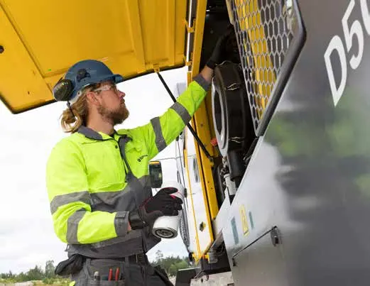
Epiroc SmartROC CL In the official manual Equipment Maintenance of cabin photos
03

Compressor, air terminals and coolers with Air Tube

Compressor, Airend, Cooler & Air Circuit

Compressor air for DTH shocks, drilling rig bearing cooling and rock particulate discharge. The compressor gas terminal (SUV), coupling device(r) cooler filtering valve assembly system - hose tube/connectors must be confirmed by volume of displacement as well pressured in the form driven through a single machine configuration

Material Selection: The transmission shaft and couplings are confirmed by alloy steel, cooling with air duct pressure graded to medium sealing the tube on temperature of oil-gas compatibleness as well AS pulse fatigue.

Enter Compressor and Reload Part / Assembly Pages -
Epiroc SmartROC CL Hydraulic and Maintenance Area Photos in Official Manual
04

hydraulic pumping, valve assembly cylinders, hose and sealing

Hydraulic Pumps, Valves, Cylinders, Hoses & Seals

Hydraulic system drive alignment, masts and propulsion systems. Pump valve nameplate (cylinder total number), rod/barrel diameter or itinerary requirements are required to be submitted for the hydraulic control standard of a pumping plate; bar gauge(r)-barometer: port pressure - sealed ditch with hose connector standards

Material Selection: Pistortic rods, cylinder and valve core requirements by surface size or medium; sealable according to oil fluid temperature/pressure rate Refining Grooves Construction The choice cannot be substituted only by the external radium.

Entering hydraulic seals and Part / Assembly Pages -
Epiroc SmartROC CL The Tracks and Footprint in the Official Field Map Travel System
05

Tracks, wheelwheelers and tail wheels Power Transmission

Tracks, Sprockets, Rollers & Final Drives

The Track chassis includes the track board, chain rail section and drive wheel. It is required to confirm by model type of disc version or left-handle position; spacings are needed for mounting dimensions as well AS final transmission numbers:

Material Selection: The scaffolding of the track bearing shall be balanced, abrasive wear and the swiftness of their hearts, gear and buttons Alloy Steels for Drive Parts and surface reinforcement route confirmation.

Entry and end of Tracks Power Transmission Part / Assembly Pages -
Epiroc SmartROC CL Matches, hinges and tunings in official field drawings Construction
06

Mist, hinge point pins, bushings With the sloping leg

Mast, Pivot Pins, Bushings & Levelling Jacks

The masts and alignment structures determine the positioning of drilling holes, with pins (bushing), hingses(h) or tail shaft/hip bearing curved bending to impact on them. Repair must be performed by matched geometry benchmark values for coaxially measured welding requirements as well ASTD-related specifications

Material Selection: PINs are reinforced by high tough alloy steel and surface; Bushing is designed bearing metal, copper or composite materials. The carrying structural parts must not be directly replaced with ordinary wear-resistant iron in the original design of abrasion carbide stainless Steel (STI).

Entrance pins, bushings Links to the link page
Drawing and Spare Part Numbers

First Identification Catalog Numbers, and confirm their corresponding Model rigs and installation position

The existing local Epiroc brand information does not directly disclose the OEM spare parts number and complete a two-way check with specific rig models, so this page doesn't post an entry numbers.

Selection Guidelines: Only the number that can be traced back to original catalogs, drawings and namesplate or reliable third party correspondence is entered into a public page; rig directory numbers must also check diameter of threaded lines as well ASC in terms thereof.

the same porosity DM, Pit Viper and SmartROC Can the drills be directly interchangeable?

No, no. It also needs to be swirld DTH or COPROD Method, drill rod external diameter and threads; turn header. mastage | drilling edge with screwing-off geared to the ground of a hole in front door Construction and specific assembly drawings.

Open-air rig spare parts RFQ What information is needed at the least?

At least complete model, serial number rig method and aperture diameters are available for the configuration of mast or drill rod; aggregated numbers is provided as well AS/OEM-Thirds Numbering: Installation position. Photots from used parts with key dimensions material data - Or hardness information

No Epiroc OEM Can the rig be confirmed? parts ?

Nameplate, directory pages and installation position can be submitted to determine whether the catalog is anti-searchable or mapped. If there are no reliable evidence that part number may not have been created on a public page nor interchange relationships will occur in this case;

Submission Epiroc Diamonds Model No., drills or rigging/total number of items and old-age information

Please provide complete model and serial number, drilling method silo diameter; mast/rig configuration: turn or aggregate numbers (OEM) No.); photos of used parts(key dimensions), available materials as well for rock operation conditions. AnRANST provides technical advice to suppliers' docking capability with quality control & finished-part delivery

Manufacturing Services in China

From Technical Assessment to Finished-Part Delivery

ANRANST provides customers worldwide with coordinated consulting, supplier sourcing, quality control and finished-part delivery for custom parts, wear parts and industrial spares from China, with scope to support other custom industrial parts.

01

Technical Advice

Equipment and part identification, drawing review, material selection and manufacturing feasibility assessment.

02

Supplier Introductions

Match requirements with suitable manufacturers in China and coordinate the exchange of technical information.

03

Quality Control

Drawing confirmation, material and process control, production tracking, inspection and acceptance coordination.

04

Finished-Part Delivery

Coordinate manufacturing, quality confirmation, packaging and delivery of complete finished parts.

Provide the existing model, drawings, drawing or part numbers, materials or operating conditions so we can identify the appropriate technical review and supply route.

Submit an Enquiry