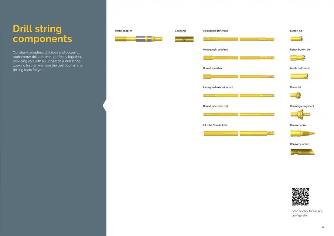
Epiroc Boltec Rock Bolting Rig Models, Tools and Essential Spares

Start with the Boltec series to identify bits and drill strings, COP rock drills, bolting units, feeds, booms, resin/grouting systems, hydraulics, chassis parts and materials for an enquiry.

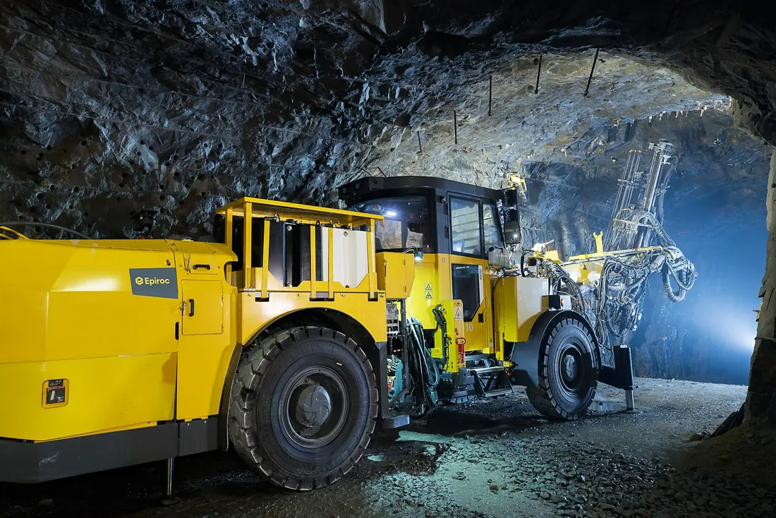
Official Epiroc photograph of a Boltec E bolting rig working underground
Official Epiroc Boltec E image showing the bolting unit, BUT 45 boom, feed, hydraulic lines, chassis and stabilizer areas.
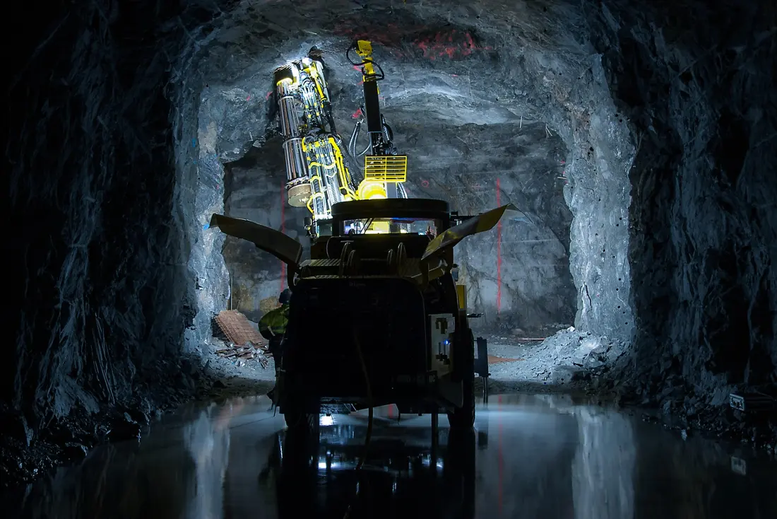
Official Epiroc photograph of a Boltec M bolting rig working underground
Official Epiroc Boltec M image for identifying medium-section operation, the bolting unit, boom and optional mesh-handling area.
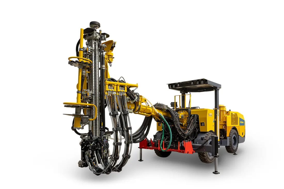
Official Epiroc image of the Boltec S10 bolting rig for small openings
Official Epiroc Boltec S10 image showing the bolting unit, feed, piping, chassis and stabilizers of this small-section rig.
OEM equipment guide

Confirm Boltec, the COP Rock Drill, Bolting Unit and Support Method Before Selecting Parts

Boltec covers low-profile, small, medium and larger openings, with S/SG variants, Auto Bolt Reload and different bolt, resin and grouting systems. Bits, shank adapters, jaws, slides, pins, bushings, cylinders and seals vary with the full model, serial number, COP rock drill, MBU/LBU/ABR unit and installation process. This page focuses on models, structures, materials and checks directly relevant to wear parts and essential spares.

8Model and installation combinations
1.8–13 mPublished support-height range
1.5–6.0 mPublished bolt-length range
12Wear-part and essential-spare categories
Models and key specifications

Boltec Models, Support Range and Key Configurations

Models follow Epiroc's rock bolting rig catalogue. The table retains only section, bolt length, rock drill, bolting unit, battery and Auto Bolt Reload information relevant to part identification.

Series / ModelOpening Size and ApplicationBolts / Key DimensionsRock Drill, Unit and Installed Configuration
Boltec SFully mechanized bolting rig for small to medium openingsBolts 1.5–3.5 m; maximum boom reach height approx. 7 mConfirm COP RR11 / RR14 and the bolting unit from nameplates
Boltec SLLow-profile headings of 1.8–2.2 mHeight approx. 1.3–1.77 m; width approx. 2.48 m; weight approx. 12.8 tCOP 628; low-profile LBU bolting unit
Boltec M10 SMedium openings; Smart seriesBolts 2.1–3.5 m; 10-bolt magazineCOP RR11, optional RR14; BUT 45 S / M
Boltec M10 SGM10 battery-tramming versionBolts 2.1–3.5 m; 10-bolt magazineSG means Smart and Green; confirm the actual power supply used during drilling
Boltec E10 SLarger openings; Smart seriesBolts 2.1–6.0 m; 10-bolt magazineCOP RR11, optional RR14; BUT 45 S / M
Boltec E10 SGE10 battery-tramming versionBolts 2.1–6.0 m; 10-bolt magazineSG means Smart and Green; identify battery, charging and high-voltage parts by serial number
Boltec M10 / E10 Auto Bolt ReloadAutomatic bolt-reloading systemFeed magazine: 8 bolts + onboard rack: 44 bolts; M10 2.4 m, E10 2.4 or 3.0 mConfirm the installed combination of S / SG and M10 / E10
Boltec S10Fully mechanized bolting rig for small openingsSuitable bolt lengths: 1.5–2.4 mConfirm rock drill, bolting unit and chassis configuration from nameplates
Legacy or regional machines such as Boltec 235 still require service but should not be presented as current global catalogue models. Check their parts separately using the full model, serial number, COP and bolting-unit nameplates, and original catalogue.
Epiroc

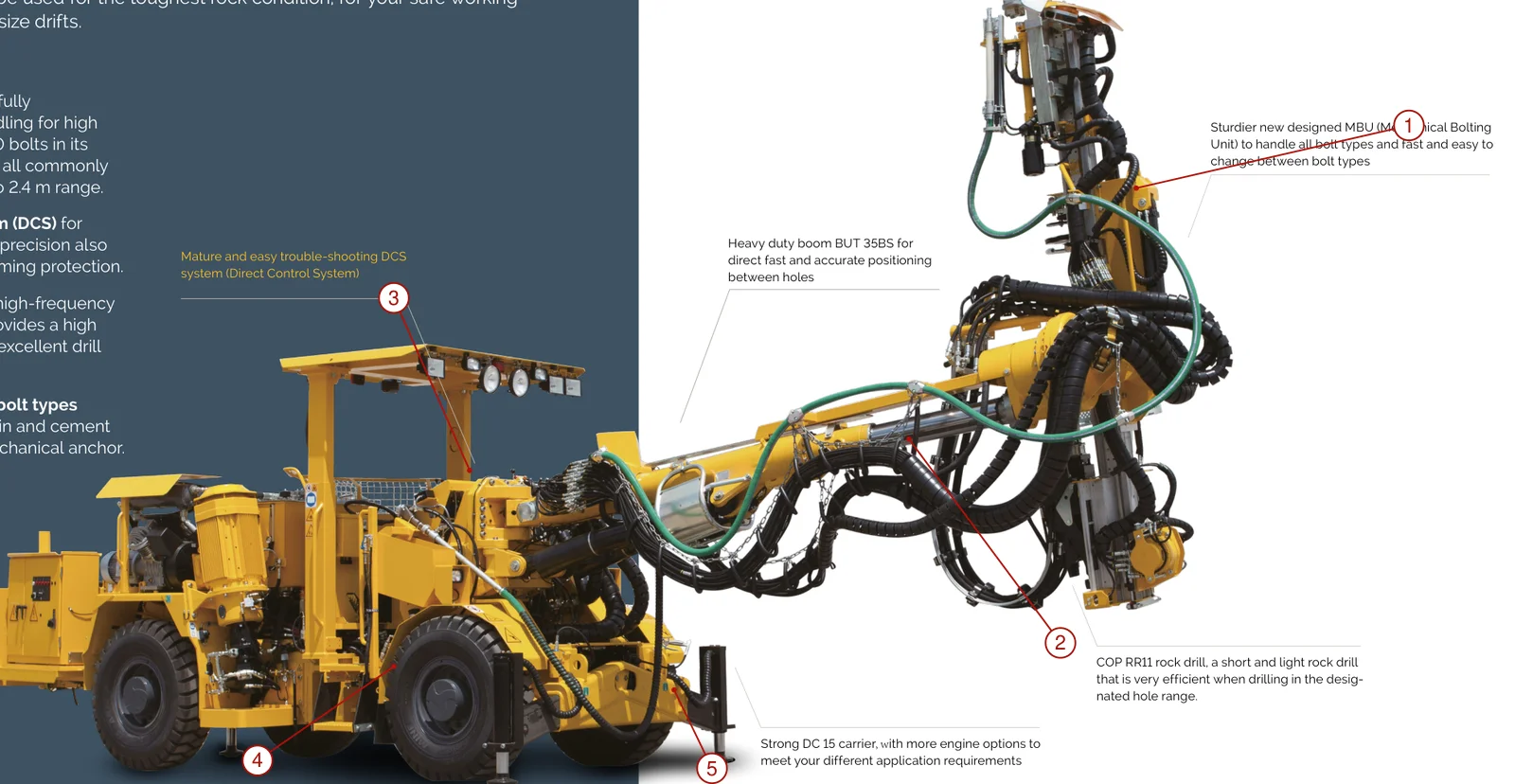
Component Location Diagram

The numbers on the diagram correspond one to one with the rows below.

Epiroc Boltec Rock Bolting Rigs – Component Location Diagram
No.ComponentLocationApplies to
1Bolting unitVertical unit at the boom tipBoltec 235
2Bolting boomBetween carrier and bolting unitBoltec 235
3Operator canopyAbove the operator positionBoltec 235
4TyreRear axle wheelBoltec 235
5Front stabilizerBelow the base of bolting boomBoltec 235
Wear parts

Bits, Drill Strings, Rock-Drill Front Ends, Bolting Units, Feeds and Pivot Wear Areas

Material links support engineering selection of ANRANST replacement parts; they do not imply one OEM material across all Boltec machines. Confirm the choice using rock properties, impact, threads, grout medium, support method, failure mode, used-part inspection and drawing requirements.

Official Epiroc photograph of Boltec E bolting operations
03

Rock-Drill Front-End Guides, Splines and Flushing Wear Parts

Rock-drill Front-head Guides, Splines & Flushing Wear Parts

Front-end guides, splines, flushing passages and seals face high-frequency impact, rotary friction, water and rock dust. The machine image locates the area; confirm guide and chuck sleeves, seals and flushing parts from the COP nameplate and sectional drawing.

Explore guides, bearings and bushings →
Official Epiroc image showing the Boltec S10 bolting unit, centralizer and magazine
04

Bolting-Unit Jaws, Centralizers and Magazine Guides

Bolting-unit Grippers, Centralizers & Magazine Guides

Jaws, centralizers, rotary heads, bolt feeders and magazine guides repeatedly handle rods, bolts and plates under impact, off-center loads, rock dust and grout exposure. Confirm the MBU, LBU, ABR or S10 unit, bolt type, length and position.

Explore gripping parts, pins and connections →
Official Epiroc working view of the Boltec M feed and boom
05

Feed Slides, Guides, Wear Strips and Thrust Blocks

Feed-beam Slides, Guides, Wear Strips & Thrust Blocks

The feed supports reciprocating motion of the rock drill and bolting unit. Slides, guides, wear strips and thrust blocks face off-center loads, rock dust, flushing water and grout contamination. Check the feed section, stroke, hole spacing, clearance and wear reference.

Explore guides, wear strips and plates →
Official Epiroc photograph of Boltec E boom, mesh-handler and stabilizer areas
06

Wear Pairs at Boom, Mesh-Handler and Stabilizer Pivots

Boom, Mesh-handler & Jack Pivot Wear Pairs

Pins, bushings, thrust parts and telescopic guides in the boom, optional mesh handler and stabilizers face alternating bending, impact and sliding wear. Check BUT 45 or the specific arm, left/right position, shaft diameter, length, lubrication grooves, housing bore and clearance.

Explore pins, bushings and connections →
Spare parts

Essential Rock-Drill, Bolting, Grouting, Boom, Chassis and Hydraulic Spares

Drive, support and seal parts are listed separately. S, SL, M10, E10, S10, S/SG and ABR configurations differ in bolting units, chassis, hydraulics, electrics and controls. Identify spares against the full model, serial number, assembly nameplate and installation position.

Official Epiroc view of the Boltec E resin and grouting system area during bolting
03

Pumps, Valves and Seals for Resin, Grout and Cement Systems

Resin, Grout & Cement-system Pumps, Valves & Seals

Pumps, metering devices, mixers, valves, hoses, nozzles and seals are not interchangeable between resin-cartridge insertion, pumpable resin, SDA/hollow-bolt grouting and automatic cement systems. Specify the medium, mix ratio, pressure, flow, temperature and cleaning method.

Explore pump/valve seals and engineering materials →
FAQ

Frequently asked questions

Are Boltec drilling tools and bolting-unit parts interchangeable by series alone?

No. Confirm the full model, serial number, COP rock drill, thread and hole diameter, MBU/LBU/ABR unit, bolt length and type, resin/grouting system and installation position together.

What information is needed for a Boltec spare-parts enquiry?

Provide the full model and serial number, S/SG version, COP and bolting-unit nameplates, bolt and grouting method, drawings or samples, used-part photographs, critical dimensions, current material and failure details.

Can a part be identified without an Epiroc OEM number?

Submit machine, COP and bolting-unit nameplates, catalogue pages, used-part markings, photographs, critical dimensions and drawings. These establish whether catalogue lookup, sample inspection or measurement is feasible. We do not invent references or interchangeability without reliable evidence.

Submit Boltec, COP, Bolting-Unit or Part Details

Provide the full model and serial number, S/SG version, COP rock drill, MBU/LBU/ABR unit, bolt and resin/grouting method, drawings or samples, used-part photographs, critical dimensions, current material and site conditions. ANRANST provides technical advice, supplier coordination, quality control and finished-part delivery.

Equipment Brand and ModelDrawingDrawing or DimensionsCurrent MaterialPhotographs of Failed PartsTarget Service LifeOperating Conditions
Request a Quote

Or contact us directly: +86 156 3797 3199
zzx@anranst.com

Manufacturing Services in China

From Technical Assessment to Finished-Part Delivery

ANRANST provides customers worldwide with engineering assessment, production at certified foundries to the customer technical requirements, quality control and finished-part delivery for custom wear parts and industrial spares, with scope to support other custom industrial parts.

01

Drawing and Engineering Review

We review mating surfaces and interface dimensions and assess material, heat treatment and manufacturing feasibility.

02

Material and Heat-Treatment Specification

Material grades and heat-treatment processes are specified order by order, stated in the technical agreement and tracked through production.

03

Quality Control

Drawing confirmation, material and process control, production tracking, inspection and acceptance coordination.

04

Finished-Part Delivery

We coordinate manufacturing, quality confirmation, packaging and delivery of complete finished parts in a workable, closed-loop supply process.

Provide the equipment brand, complete model and serial number, part name, part number or drawing number, drawing revision, quantity, material requirements and duty. If identifiers are unavailable, send photographs and key dimensions.

Submit an Enquiry