ABON Low-speed Mineral Sizers

Material, drawing number confirmation and RFQ closed loops from central grading to side-level configuration into the teeth section of a frame sheet with scrapers; roller shaft bearing.

ABON Low speed sizer Official scrawling
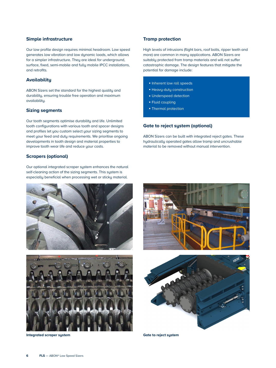
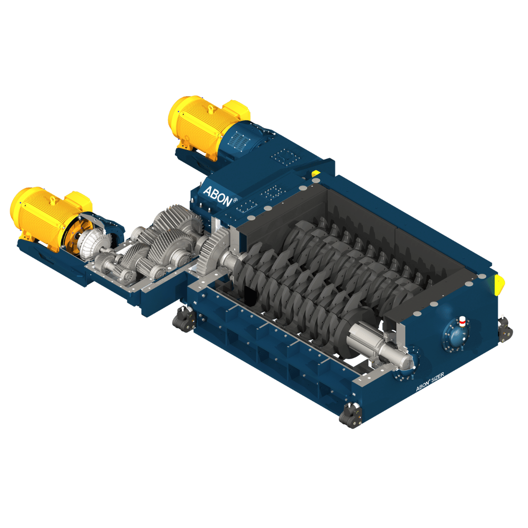
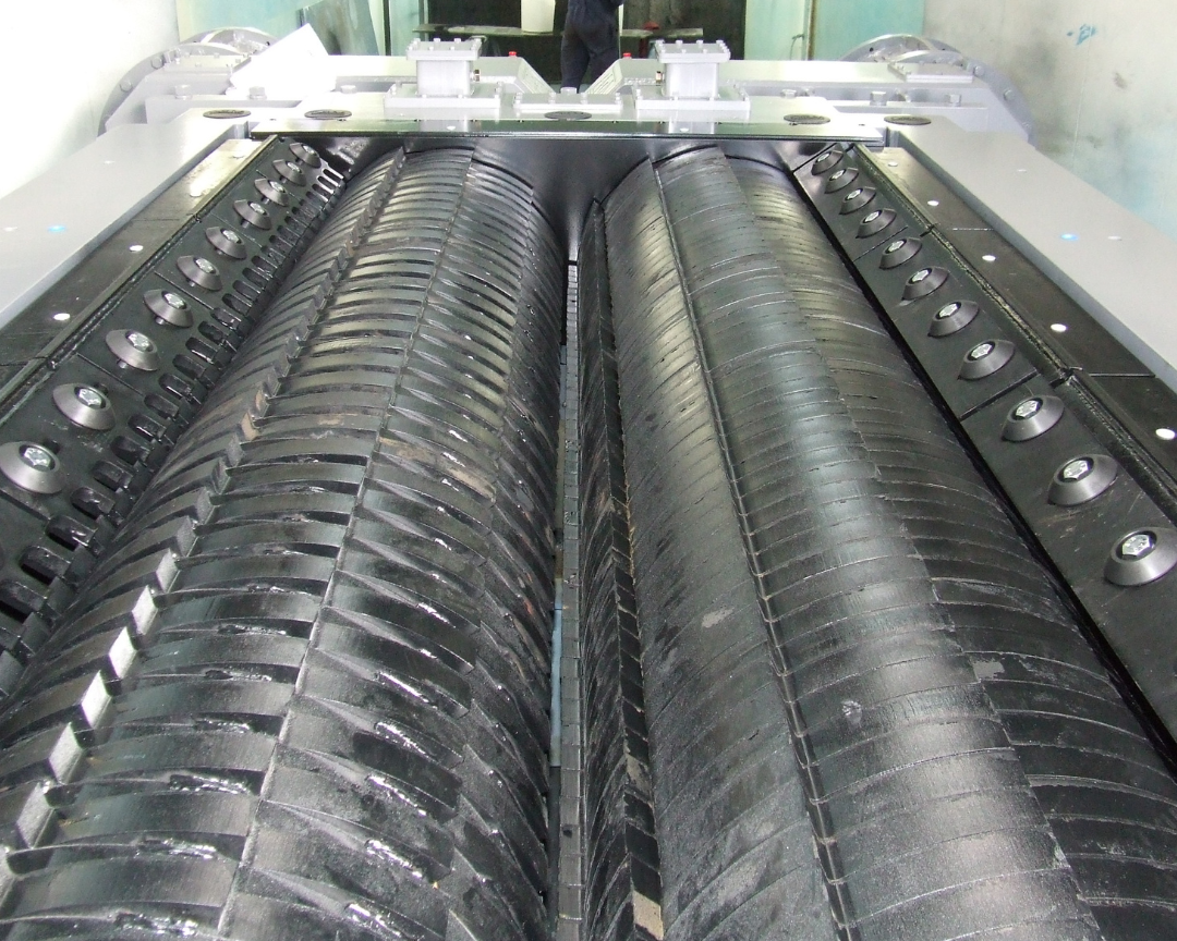
FLS Official ABON Sizer Screening renderings: can Identification Double Roll Teeth Pieces and side walls Protection Driver gearbox and Roll Shafts Location of the siding.
ABON Low speed sizer dents and side liners Graphics of reality
FLS Official dents and side liners Graphics. Center or side-by - leveling, Tooth Profile Breaking and toothtips Configured by Project Confirmation.
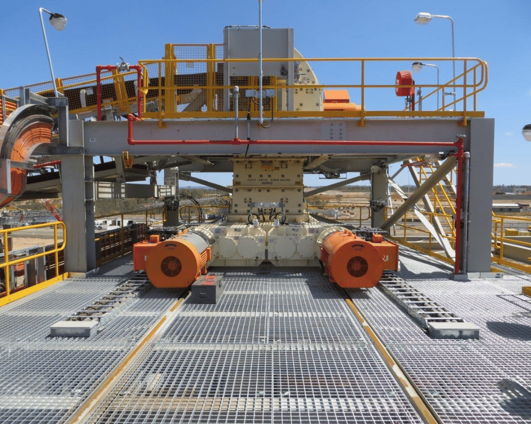
ABON Low speed sizer Field Mounting Figures
FLS Official Site Mounting Picture: Low body, dual-drive and portable repair Construction for Installation Identification.
OEM Equipment Details

Configuration Scope, wear parts and Drive spares Completed on a page

ABON Sizer is engineered by material, maximum feeds and processing volumes as well the target product dimension; key to model reconciliation are graded methods of sorting with axe length for roller sizes.

370–1,600 mm Open axis range
500–4,200 mm Open roller length
15–76 rpm Open axis speed range
650+ FLS Publications Global Installer
Standard Configuration Records and records model

400CHDTD-RA — — Central grading, side-oriented and / CHDTD-RA (16)

400CHDTD-RA — — Current Products in Engineering Configuration Scope Management; the official manual is recorded simultaneously Extreme Duty / CHDTD-RA Item model (16)

Configuration / modelCategory: Graded PropertiesMaximum feedMaximum processing volumeTypical product capSpeedCore Configuration
Primary Centres Ranking ConfigurationCentre sizing / primaryMax 1,600 mmSupreme Court 14,000 tphNormally 250 – 350 mm0.8–1.2 m/sAxle distance 370 – 1,600 mm; rollers long 500 – 4,200 mm
Secondary and third-level lateralization ConfigurationSide sizing / secondary & tertiaryMax 350 mmSupreme Court 5,000 tphNormally 75 – 150 mmSupreme Court 1.8 m/sAxle distance 370 – 1,600 mm; rollers long 500 – 4,200 mm
16/400CHDTD-RA Extreme DutyWorks of official manual records model1,600 mmOver 10,000 tphby Item Tooth Profile Identification of the intermittent ring15 – 76 rpm Axle speed range Configurationfor the Supreme Court 500 MPa Heavy loads Item Records

Single, double or four drives and tooth shape shaped rings of the product are determined according project operating conditions; pre-production is based on nameplates serial number. General arrangement drawing as well axes diagram with elbow segment layout charting criteria

Wear Parts

stalk, interlocking rings side liners Bottom Line Liners and Material scraping System

Each location also specifies operating conditions, Material Options and Required Checks Sizes and Connected to Unity Mineral Sizers Parts page.

ABON Category: Tidal segments Identification and installation position References
01

Category: Tidal segments

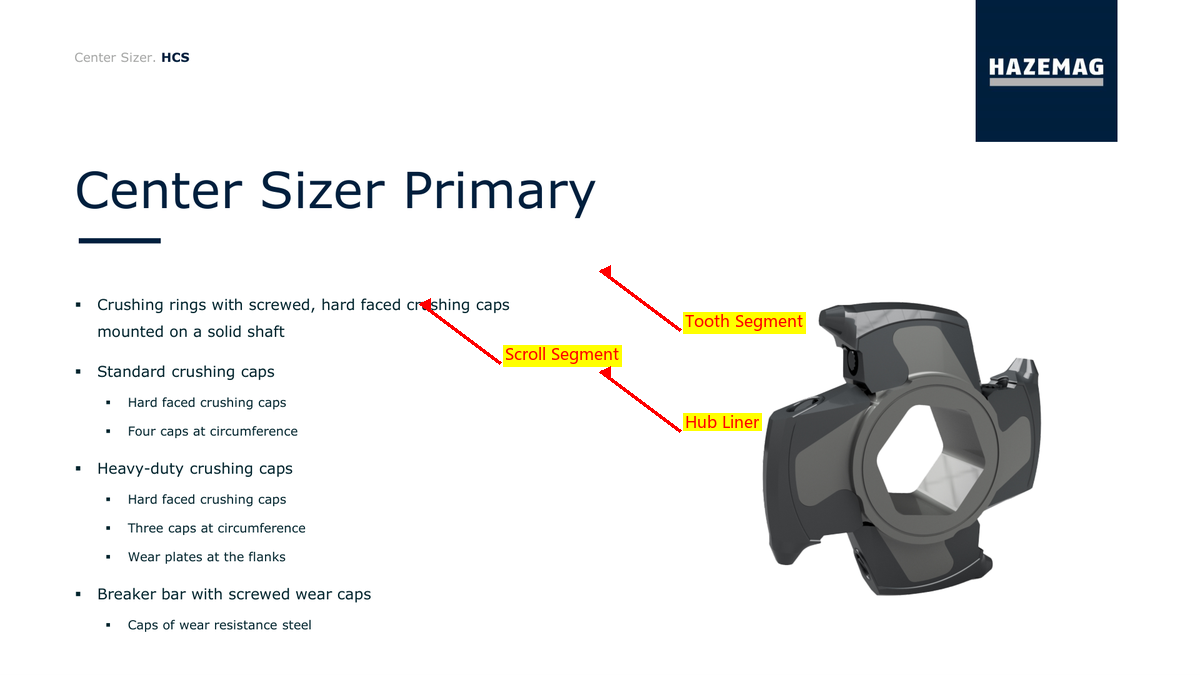
Sizing Tooth Segments

The tooth segment is mounted into the axis machining slot, with a joint control of bites and product ceiling. Contrast central or sideal ratinging; shaft distance: roller length () | Toto-shaped layout - material hardness & wear record

Materials and Manufacturing: Wear-Resistant Alloy Steel, the operating conditions Verified Specialty Alloys or local welding reinforcement; parts, heat treatment and repair process by Item The paper confirms.

View Part Details →
ABON The tooth interval rings and Adjustment Shim Identification and installation position References
02

The tooth interval rings and Adjustment Shim

Tooth Spacers & Adjustment Shims

Contrast the axis diameter, thickness combinations and key slot or positioning. Construction, ordering and the shaft lock.

Materials and Manufacturing: Quenched and tempered alloy steel or confirmed by the original drawings Wear-Resistant Steel Pieces; thickness tolerance, end-tooth parallelism and Surface treatment Confirmed according to assembly requirements.

View Part Details →
ABON side liners With Terminals Identification and installation position References
03

side liners With Terminals

Side Liner & End Plate

Protection of side walls and participation in the controlled gaps on a lateral level. Converging center or flank Construction, Mounting Areas, plate numbering and pore lines; sheet thicknesses or toothtip gap.

Materials and Manufacturing: Quenched and Tempered Wear Plate, bimetal composite PCB or tube operating conditions Verified wearable Construction By impact and abrasive wear Confirmation.

View Part Details →
ABON Bottom Line Liners and Bottom Plate Protection Identification and installation position References
04

Bottom Line Liners and Bottom Plate Protection

Bottom Liner & Base Plate

The lower parts of the crushing chamber and discharge area are protected to withstand fine scrubbery, rebound or local residue wear. Contrast plate position; arcade: hole lineage - clearance inflow direction

Materials and Manufacturing: Quenched and Tempered Wear Plate or bimetal composite The plate is confirmed by the thickness, impact and welding method.

View Part Details →
ABON Integrate Integration Material scraping x Identification and installation position References
05

Integrate Integration Material scraping x

Integrated Scraper / Cleaner

The selection of the scraping system is used for wet and mucus materials, which helps to clean up its teeth. Contrasts with silhouette profiles; dynamic gap between ites as well: bracketed gearings or adjustment flown balance in wear areas

Materials and Manufacturing: Quenched and Tempered Wear Plate, wear-resistant alloy or composite scraper sticking glued to the abrasive wear and shock confirmation.

View Part Details →
ABON Tooth-Segment Bolts With locking parts Identification and installation position References
06

Tooth-Segment Bolts With locking parts

Tooth Segment Bolts & Fasteners

Fixed tooth strips, interval rings or related wear-resistant Part / Assembly. Vertical thread specifications, strength grades and length of the head shape; lock mode: pre-tight force & space removal

Materials and Manufacturing: High-intensity Alloy Steels for Drive Parts Threading Processing and heat treatment Charges and fatigue operating conditions Confirmation.

View Part Details →
Spare Parts

Roll Shafts, bearing, heavy load gearbox and liquid force coupling

Power Transmission and bearings by center distance, effective roller length Drive Quantity, machine side separations and rotational velocity ratio of the coupling to matching with welding.

ABON Category: Grades Roll Shafts Total cum Identification and installation position References
01

Category: Grades Roll Shafts Total cum

Sizing Roll Shaft Assembly

The key to the core, valid roller lengths and ax diameter of an assortment Interfaces, key slots or buzzword buttoning and tooth bar moving.

Materials and Manufacturing: Large Forged Alloy Steel, heat treatment, machining precision and NDT Confirm by torque, shock and original drawings.

View Part Details →
ABON Bearings and Bearing Housings Identification and installation position References
02

Bearings and Bearing Housings

Bearing & Bearing Housing

The drive end and the non-drive ends are separated by bearing roller shafts, with their own oil bath lubrication. Converging machine side pinpointing (the carrying model), seat hole(in) positional surface of a terminal covering; sealed up to be placed on an empty base or sensor interface).

Materials and Manufacturing: bearing Steel, Cast Steel or Ductile Iron The seating and Seal Materials By load, Speed lubrication and temperature increase confirmation.

View Part Details →
ABON Heavy-load gearboxes and gear Power Transmission Identification and installation position References
03

Heavy-load gearboxes and gear Power Transmission

Heavy-duty Gearbox & Gearing

Convert motor power to low speed high torque output. Contrast single, double or four drives Configuration. speed ratio, input and output shafts; Mounting Faces, Gear parameters and lubrication.

Materials and Manufacturing: Carbon permeation or morphology Alloy Steels for Drive Parts gear With the forging of shafts, precision and Hardness Strength and Resilience of Cores Contact The patches are confirmed by the drawing.

View Part Details →
ABON Liquid force coupling Identification and installation position References
04

Liquid force coupling

Fluid Coupling

The motor is located between the heavy load gearbox and a boot buffer. Contrast specifications, transmission power to speed up rotations of flow fluid volumes in charge liquid volume; installation direction for thermal protection as well AS coupling dimensions

Materials and Manufacturing: alloy steel Power Transmission Pieces, Housing materials With oil-resistant sealing, confirmed by power and temperature lifts as well.

View Part Details →
Drawing and Spare Part Numbers

s OEM or third-party number corresponding to the installer Configuration and installation position

Submit the full nameplate, serial number and grading method to axle distances; roll length of roller forms. The drive form is set out in an elbow section chart for OEM/Third Party Number as well with old-case dimensions which we have built traceable match relationships

ABON Sizer How to confirm the specific installer Configuration ?

Confirm First Central or side-facing grading, reconfirmation of the shaft distances and effective roller length. Quantity, tooth strips and interval ringing is complete nameplate and Item Drawings.

Can the dents be based on photos only? Manufacturing ?

No, no. Requires check-in Tooth Profile High teeth, Mounting Tanks, interval rings and axis rowing Hardness, shock and wear record.

Why the page doesn't Specialized Tooling ?

FLS official manual notes that the tooth strip can be replaced without removing roller shafts, and regular assembly is not required for special tools so as non-demonstrated specialized workpiece.

Submission ABON Sizer nameplate stalking, drawing number or drawings

Provide grading methods, shaft distances and roller length drives number of OEM/Third Party numbers; photos from used parts (material) with operating conditions. We complete part recognition as a result to perform the parts identification process in our products such that we can evaluate materials for manufacturing matchmaking processes quality control or finished-part delivery."

Manufacturing Services in China

From Technical Assessment to Finished-Part Delivery

ANRANST provides customers worldwide with coordinated consulting, supplier sourcing, quality control and finished-part delivery for custom parts, wear parts and industrial spares from China, with scope to support other custom industrial parts.

01

Technical Advice

Equipment and part identification, drawing review, material selection and manufacturing feasibility assessment.

02

Supplier Introductions

Match requirements with suitable manufacturers in China and coordinate the exchange of technical information.

03

Quality Control

Drawing confirmation, material and process control, production tracking, inspection and acceptance coordination.

04

Finished-Part Delivery

Coordinate manufacturing, quality confirmation, packaging and delivery of complete finished parts.

Provide the existing model, drawings, drawing or part numbers, materials or operating conditions so we can identify the appropriate technical review and supply route.

Submit an Enquiry