
What other names or designations is the Air-swept ball tube mill known by?
The Air-swept ball tube mill is also documented under these designations: KVS air-swept ball / tube mills, KVS Kendal 15 5 ×22 1, KVS Kendal.
Air swept ball tube mill · 2006 · 1 model
Select a model to jump to its component table; former and renamed designations are listed under “Historical names / renamings”.
| Model | Historical names / renamings | Period | Components |
|---|---|---|---|
| KVS air-swept ball / tube mills | KVS Kendal 15 5 ×22 1; KVS Kendal | 2006 | 71 |
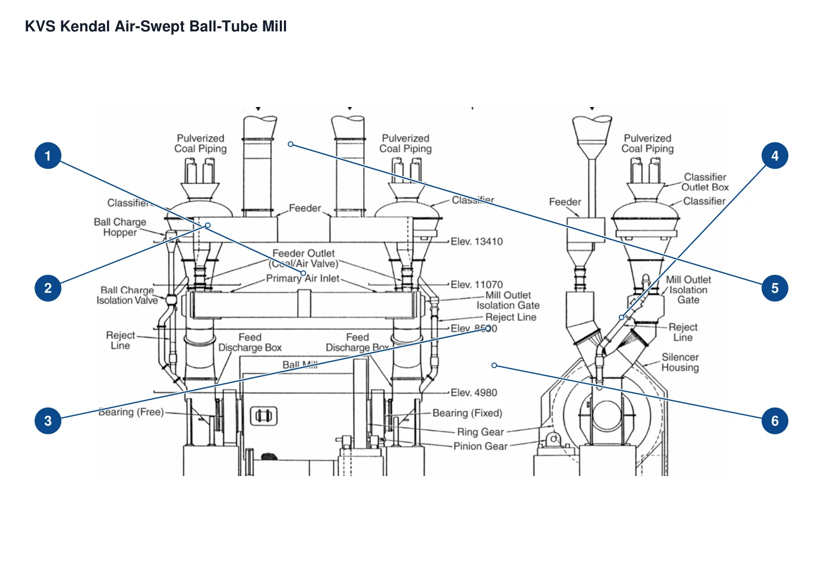
The numbers on the diagram correspond one to one with the rows below.
| No. | Component | Location | Applies to |
|---|---|---|---|
| 1 | Feed / discharge boxes | Connection box at the left end of the mill in the side view | Kendal: 15ft 5in x 22ft 1in, double-ended air-swept tube ball mill installation |
| 2 | Ball-charge hopper | Ball-charge hopper above the left-hand end in the side view | Kendal: 15ft 5in x 22ft 1in, double-ended air-swept tube ball mill installation |
| 3 | Girth gear | Outer circumference at the right-hand mill end in the side view | Kendal: 15ft 5in x 22ft 1in, double-ended air-swept tube ball mill installation |
| 4 | Silencer housing | Enclosure around the mill in the right-hand end view | Kendal: 15ft 5in x 22ft 1in, double-ended air-swept tube ball mill installation |
| 5 | Mill connecting ductwork | Inlet ductwork from the coal bunker in the side view | Kendal: 15ft 5in x 22ft 1in, double-ended air-swept tube ball mill installation |
| 6 | Trunnion bearings | Support beneath the mill end in the side view | Kendal: 15ft 5in x 22ft 1in, double-ended air-swept tube ball mill installation |
| Component |
|---|
| Feeding box lining |
| Hollow bushing |
| steel ball |
| Pinion Bearing |
| Main drive reducer |
| Falk high speed and low speed coupling |
| Forced lubrication oil tank |
| Forced lubrication gear pump |
| Lubrication pump drive motor |
| Double basket oil filter |
| Tubular oil cooler |
| Oil distributor inside the reduction gearbox |
| Forced lubrication pressure relief valve group |
| Ring gear automatic grease lubrication system |
| Grease spray air solenoid valve |
| Ring gear grease pump |
| Ring gear air atomization nozzle |
| Turning worm reducer |
| Turning drive motor |
| Turning magnetic brake and brake drum |
| Turning gear coupling |
| Classifier high wear surface ceramic patch |
| Coarse powder return pipe inclined section lining |
| Silencer shell thermal insulation and sound insulation layer |
| Silencer shell access door |
| Silencer shell inspection hole cover |
| Ball filling hopper isolation valve |
| Ball replenishing hopper chute |
| Sealed air fan |
| Sealed air blower motor |
| Sealed fan intake silencer filter group |
| Sealed fan gear coupling |
| Pinion shaft seal |
| Pinion seal water seal ring |
| Pinion shaft stuffing box |
Models with the same components are grouped together; select a group to open its component table.
| No. | Component | Location |
|---|---|---|
| 1 | Feeding and discharging box body | Material inlet and outlet connection; the original registered liner is retained. |
| 2 | Steel ball loading hopper body | The hopper for replenishing balls to the mill. The two ball charge hoppers in the text are summarized by one part. |
| 3 | Girth gear | External drive side of grinding shell |
| 4 | Silencer housing | mill silencer housing |
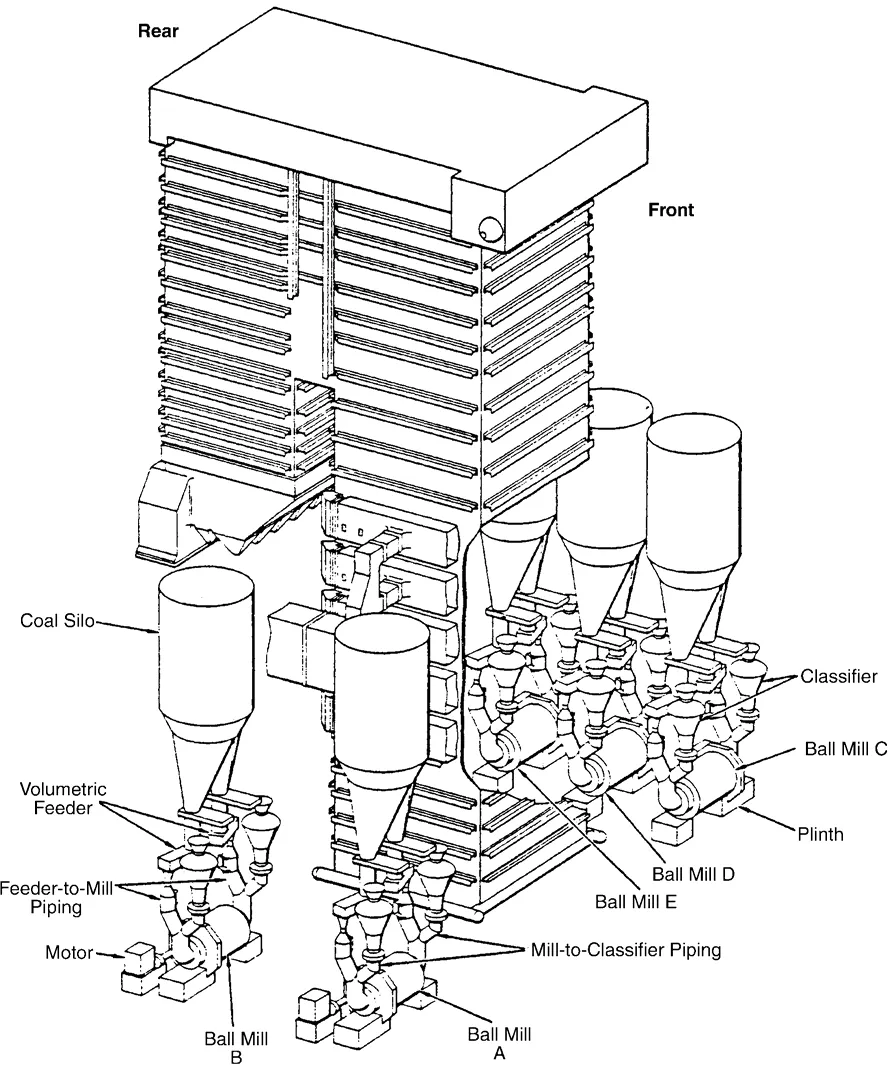
| 5 | Mill connecting duct air duct group | Three paths from the feeding valve to the mill, the mill discharges to the classifier, and the coarse powder returns to the feeding box |
| Feeding box lining | Feeding box discharge side and feeding plate | |
| Hollow bushing | The inside of the mill inlet and outlet journal | |
| steel ball | Inside the mill barrel | |
| Pinion Bearing | Drive pinion support | |
| Main drive reducer | Mill transmission chain; Chapter 7 single-stage helical gear | |
| Falk high speed and low speed coupling | Main drive high speed/low speed side; two similar positions are registered together | |
| Forced lubrication oil tank | Under the reducer and pinion bearing lubrication system | |
| Forced lubrication gear pump | The oil tank supplies oil and supplies pressure oil to the reduction box and pinion bearings. | |
| Lubrication pump drive motor | Gear pump drive | |
| Double basket oil filter | After the pump, before the oil cooler | |
| Tubular oil cooler | Oil supply to main reduction box and pinion bearing after filter | |
| Oil distributor inside the reduction gearbox | Internal oil supply of main reduction gearbox | |
| Forced lubrication pressure relief valve group | Filter/cooler bypass and pressure adjustment | |
| Ring gear automatic grease lubrication system | Grease spraying on the pressure tooth surface of the ring gear | |
| Grease spray air solenoid valve | Controlled by electrical switch board timer | |
| Ring gear grease pump | Pneumatic pump supplies grease from 50 or 180kg grease container; two container specifications are optional | |
| Ring gear air atomization nozzle | Grease spraying on the pressure tooth surface of the ring gear | |
| Turning worm reducer | barring gear system | |
| Turning drive motor | Turning worm reducer drive | |
| Turning magnetic brake and brake drum | Between motor and worm reducer | |
| Turning gear coupling | Worm reducer low speed shaft and one end of double output shaft motor | |
| Classifier high wear surface ceramic patch | High wear surface of classifier | |
| Coarse powder return pipe inclined section lining | Inclined section leading to mill feed box | |
| Silencer shell thermal insulation and sound insulation layer | Insulation/sound insulation structure within the sound-absorbing shell that meets the 85dB(a) requirement for this example | |
| Silencer shell access door | Silencer shell access door | |
| Silencer shell inspection hole cover | inspection hole with cover; hole is not regarded as another part | |
| Ball filling hopper isolation valve | The connection between the hopper and the ball filling machine | |
| Ball replenishing hopper chute | Hopper to mill feeding/discharging box | |
| Sealed air fan | Sealing air supply for various parts of the mill; supporting the mill system | |
| Sealed air blower motor | Fan driver | |
| Sealed fan intake silencer filter group | Air intake silencer with filter | |
| Sealed fan gear coupling | Fan drive connection | |
| Pinion shaft seal | pinion gear seals in checklist | |
| Pinion seal water seal ring | lantern rings, seal inspection object; descriptive Chinese name reserved in English | |
| Pinion shaft stuffing box | stuffing box alignment/gap check | |
| Ring gear lubrication drip pan | drip trays need cleaning | |
| Grease spray distribution proximity switch | Monitoring the moving plunger, the example clearance is given in the table | |
| Grease dispensing moving plunger | moving plunger, opposite to proximity switch | |
| Grease injection system filter | Clear objects in the trainers table | |
| Ring gear sealing device | girth gear sealing arrangement integrity/air leakage inspection in the table | |
| Reduction box coupling protective cover | Table 19-11 Disassembly and assembly of high-speed/low-speed coupling protection | |
| Reduction box coupling spring | The high-speed/low-speed coupling disassembly and inspection list clearly indicates coupling springs; do not create a new coupling series based on this | |
| Reduction gearbox upper and lower half shells | Remove the upper half shell, clean both halves and then reassemble | |
| Reducer box joint surface positioning pin | Two M20 positioning pins for casing joint | |
| Reduction gearbox input end cover | input line end cover | |
| Reduction gearbox fuel injection gun barrel | Remove the oil spray lance flange joint | |
| Reduction box pinion shaft | pinion shaft lifting out inspection | |
| Reduction box oil seal | Oil seals removed after removing the labyrinth cover | |
| Reduction box shaft stop plate | keeper plate is located at the non-drive end | |
| Reduction box shaft locking nut | drive end locknut | |
| Reduction gearbox input and output bearing set | The table specifies the axial clearance of the bench and installation respectively; the quantity/type is not completely listed | |
| Reduction box output shaft assembly | Lift the output shaft assembly vertically from the box | |
| Gasket for central joint surface of reduction gearbox | Central joint surface of composite cabinet | |
| Double cone classifier | Mill exhaust pulverized coal classification system | |
| Forced lubrication control monitoring instrument cluster | Pressure switch, thermometer, flow indicator, pressure gauge, thermostat and sensor alarm | |
| Grease injection compressed air treatment group | Filtration, pressure regulation and lubrication before grease injection pump | |
| Grease injection progressive single line distributor | Grease separation at the rear of the pump towards the nozzle | |
| Grease injection timing and alarm control system | Electrical switch board timing, low air pressure/nozzle line high pressure/pump duration abnormal alarm and shutdown interlock | |
| Double cone classifier manually adjustable blade set | Manual adjustment of blades in classifier | |
| Double cone classifier guide vane set | deflector vanes | |
| Double cone classifier inner and outer cones | Composition of inner and outer cones of classifier | |
| Classifier coarse powder return pipe | reject line connected to mill feed box | |
| Classifier coarse powder cut-off gate | cut-off gate on coarse powder return pipe | |
| Mill bypass vent door assembly | mill bypass damper assemblies | |
| Reduction gearbox oil collector | oil catcher | |
| Reduction gearbox oil collector labyrinth cover | labyrinth cover removed from oil collector |
The Air-swept ball tube mill is also documented under these designations: KVS air-swept ball / tube mills, KVS Kendal 15 5 ×22 1, KVS Kendal.
The Air-swept ball tube mill is listed under the Kennedy Van Saun brand as: Air swept ball tube mill. Period: 2006. Status: Historical model.
71 components are recorded, including: Feeding box lining, Hollow bushing, steel ball, Girth gear, Pinion Bearing, Feeding and discharging box body, Steel ball loading hopper body, Main drive reducer and more. The full list with locations is in the components table on this page.
Model-specific components with their own page: Double cone classifier, Forced lubrication control monitoring instrument cluster, Grease injection compressed air treatment group, Grease injection progressive single line distributor, Grease injection timing and alarm control system, Double cone classifier manually adjustable blade set, Double cone classifier guide vane set, Double cone classifier inner and outer cones and more (13 in total).
Send us a drawing or sample and tell us the equipment model and part name.
Provide the equipment model, drawing for engineering review and quotation. If service life or wear is a concern, describe the operating conditions as well.
Or contact us directly: +86 156 3797 3199
zzx@anranst.com
ANRANST provides customers worldwide with engineering assessment, production at certified foundries to the customer technical requirements, quality control and finished-part delivery for custom wear parts and industrial spares, with scope to support other custom industrial parts.
We review mating surfaces and interface dimensions and assess material, heat treatment and manufacturing feasibility.
Material grades and heat-treatment processes are specified order by order, stated in the technical agreement and tracked through production.
Drawing confirmation, material and process control, production tracking, inspection and acceptance coordination.
We coordinate manufacturing, quality confirmation, packaging and delivery of complete finished parts in a workable, closed-loop supply process.
Provide the equipment brand, complete model and serial number, part name, part number or drawing number, drawing revision, quantity, material requirements and duty. If identifiers are unavailable, send photographs and key dimensions.
Submit an Enquiry