
What other names or designations is the Mill known by?
The Mill is also documented under these designations: KVS mineral processing mill, KVS, KVS 11ft×20ft, KVS 9ft×12ft6in Ball mill, KVS 10ft×10ft6in Ball mill.
Grinding mill · 1 model
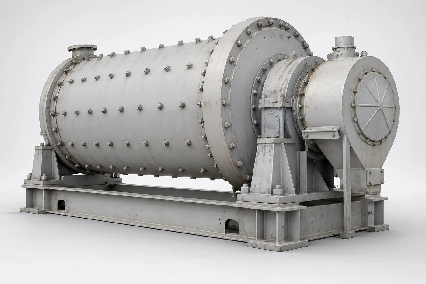
Select a model to jump to its component table; former and renamed designations are listed under “Historical names / renamings”.
| Model | Historical names / renamings | Components |
|---|---|---|
| KVS mineral processing mill | KVS; KVS 11ft×20ft (1960Picton); KVS 9ft×12ft6in Ball mill; KVS 10ft×10ft6in Ball mill | 30 |
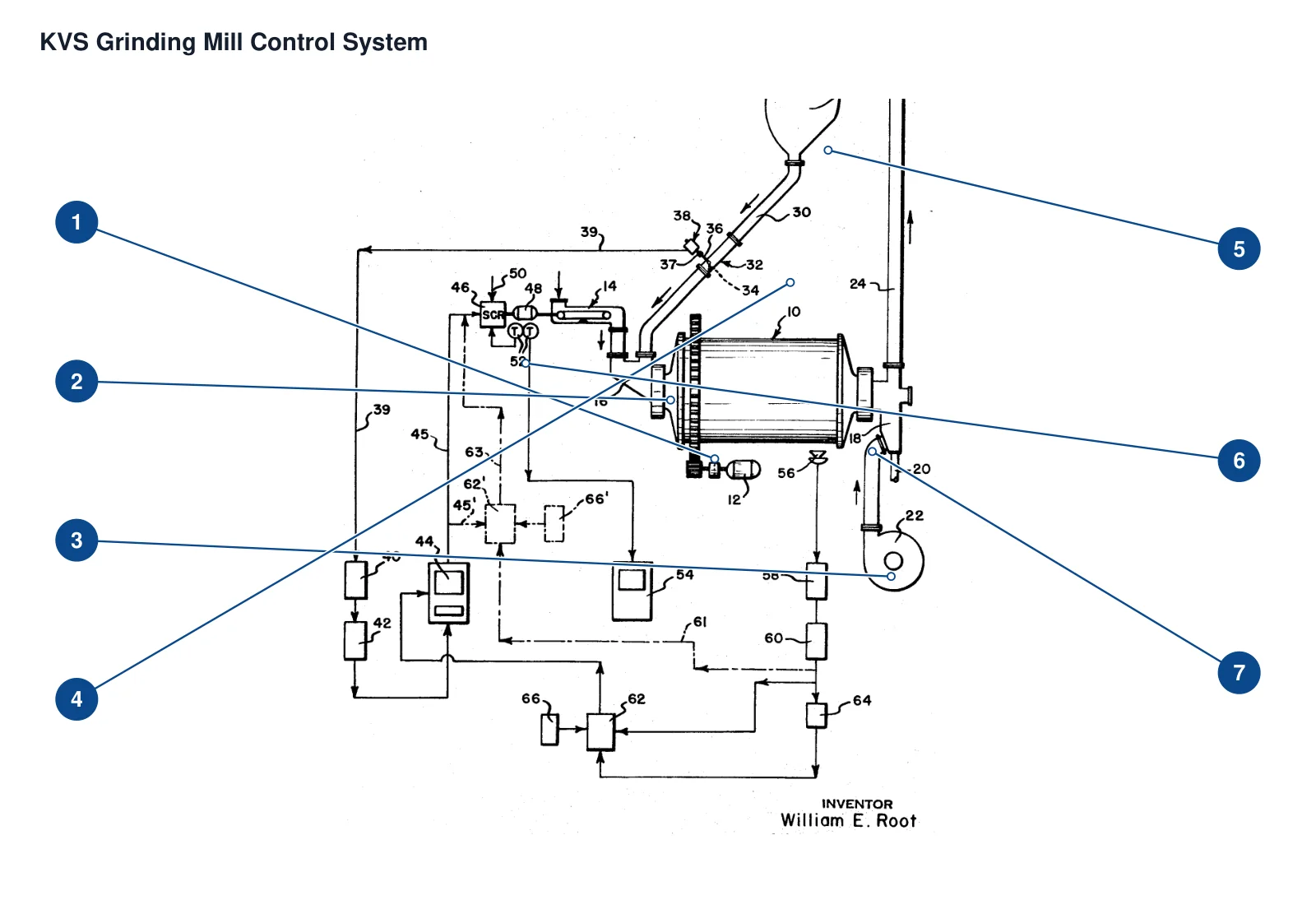
The numbers on the diagram correspond one to one with the rows below.
| No. | Component | Location | Applies to |
|---|---|---|---|
| 1 | Mill drive motor - Patent embodiment | Drive motor below the mill in the original view | US3690570 technical design embodiment; commercial mill model not specified |
| 2 | Mill inlet chute - Patent embodiment | Inlet connection at the left end of the mill | US3690570 technical design embodiment; commercial mill model not specified |
| 3 | Blower - Patent embodiment | Lower fan in the pneumatic system on the right | US3690570 technical design embodiment; commercial mill model not specified |
| 4 | Classifier reject return duct - Patent embodiment | Inclined duct from the classifier to the inlet chute | US3690570 technical design embodiment; commercial mill model not specified |
| 5 | Pneumatic conveying duct and classifier | Upper conical classifier | US3690570 technical design embodiment; commercial mill model not specified |
| 6 | Vibrating feeder and drive | Ahead of the mill inlet chute | US3690570 technical design embodiment; commercial mill model not specified |
| 7 | Fluidizing feeder | Discharge connection at the right-hand end of the mill | US3690570 technical design embodiment; commercial mill model not specified |
| Component |
|---|
| Technical design of coarse material retention screen at discharge end |
| Pivot coupling |
| Transmitter bias lever |
| Transmitter bias spring |
| Transmitter double pulley |
| Transmitter drive braided cable |
| Rotary position transmitter |
| Rotary potentiometer |
| 1960Picton KVS raw material grinding steel ball |
| Return material detection pipe section and central launder wall |
| T-shaped detection block |
| Detect the shutter pivot |
| Return material signal conditioner |
| Return material signal converter |
| Recording controller |
| Feeding drive power supply unit |
| Tachometer and feed rate recorder |
| Grinding pickup (optional protection) |
| Moyin signal conditioner and converter (optional protection) |
| Grinding sound monitoring switch (optional protection) |
| Ratio controller (protection scheme) |
| Manual output loader (protection scheme) |
| 1960Picton KVS double grinding chamber |
Models with the same components are grouped together; select a group to open its component table.
| No. | Component | Location |
|---|---|---|
| 1 | Technical design of mill drive motor | The peripheral mill driver shown in the picture does not prove the original motor of a certain KVS product. |
| 2 | Technical design feed guide | Mill import; not guide trough liner, no liner page |
| 3 | Technical design blower | Pneumatic conveying air source |
| 4 | Technical design of coarse material return inclined pipe | Classifier reject material returns to mill feed guide chute |
| 5 | Technical design of delivery airway and classifier | Process for sorting products after grinding; not certified to sell commercial graders separately |
| 6 | Technical design of vibrating feeder and drive | Mill import; motor driven vibrating feed shown in the picture |
| 7 | Technical design fluidized feeder | Material transportation after grinding, with miscellaneous iron discharge port |
| Technical design of coarse material retention screen at discharge end | Mill discharge end; screen type/aperture not documented, not equal to grate plate | |
| Pivot coupling | Connection between external position transmitter and flap shaft | |
| Transmitter bias lever | Press lightly to load the baffle | |
| Transmitter bias spring | Lever elastic loading | |
| Transmitter double pulley | The axis movement is transmitted to the potentiometer; the original text gives a ratio of 2 to 1, and does not recommend product specifications. | |
| Transmitter drive braided cable | Transmission between two pulleys | |
| Rotary position transmitter | Outside of the pivot of the return stopper | |
| Rotary potentiometer | The transmitter is driven by double pulleys. The resistance value is only an example and is not written as a product specification. | |
| 1960Picton KVS raw material grinding steel ball | The raw material grinding section is clearly 1¼-3in; the specifications of grinding balls for finished cement products from the same factory are not the same. | |
| Return material detection pipe section and central launder wall | Restrict return material flow from entering the central inspection space | |
| T-shaped detection block | Light pressure/floating on the return flow, swinging with the flow; patented mechanism | |
| Detect the shutter pivot | Cross detection pipe section | |
| Return material signal conditioner | Filter pulse/miscellaneous signals | |
| Return material signal converter | Supply signal to recording controller; 4-20mA original text example, not full series specifications | |
| Recording controller | Adjust feeding drive | |
| Feeding drive power supply unit | Motor feed control; voltages stated are specific examples only | |
| Tachometer and feed rate recorder | Motor feedback/feed rate record; do not add self-made instrument list | |
| Grinding pickup (optional protection) | adjacent grinding machine, used for abnormal grinding sound coverage control | |
| Moyin signal conditioner and converter (optional protection) | Grinding sound signal path | |
| Grinding sound monitoring switch (optional protection) | Solid line/dash line alternative wiring scheme aggregation, not recorded as two sets installed at the same time | |
| Ratio controller (protection scheme) | Grinding sound protection signal path shown in solid line | |
| Manual output loader (protection scheme) | Abnormal grinding noise reduces feeding; two wiring solutions converge | |
| 1960Picton KVS double grinding chamber | 11ft×20ft ball mill interior; two-compartment only describes these four units, not equal to two independent series |
The Mill is also documented under these designations: KVS mineral processing mill, KVS, KVS 11ft×20ft, KVS 9ft×12ft6in Ball mill, KVS 10ft×10ft6in Ball mill.
The Mill is listed under the Kennedy Van Saun brand as: Grinding mill. Status: Historical model.
30 components are recorded, including: Technical design of mill drive motor, Technical design feed guide, Technical design of coarse material retention screen at discharge end, Technical design blower, Technical design of coarse material return inclined pipe, Pivot coupling, Transmitter bias lever, Transmitter bias spring and more. The full list with locations is in the components table on this page.
Model-specific components with their own page: Technical design of vibrating feeder and drive, Technical design fluidized feeder, Technical design of delivery airway and classifier, Return material detection pipe section and central launder wall, T-shaped detection block, Detect the shutter pivot, Return material signal conditioner, Return material signal converter and more (17 in total).
Send us a drawing or sample and tell us the equipment model and part name.
Provide the equipment model, drawing for engineering review and quotation. If service life or wear is a concern, describe the operating conditions as well.
Or contact us directly: +86 156 3797 3199
zzx@anranst.com
ANRANST provides customers worldwide with engineering assessment, production at certified foundries to the customer technical requirements, quality control and finished-part delivery for custom wear parts and industrial spares, with scope to support other custom industrial parts.
We review mating surfaces and interface dimensions and assess material, heat treatment and manufacturing feasibility.
Material grades and heat-treatment processes are specified order by order, stated in the technical agreement and tracked through production.
Drawing confirmation, material and process control, production tracking, inspection and acceptance coordination.
We coordinate manufacturing, quality confirmation, packaging and delivery of complete finished parts in a workable, closed-loop supply process.
Provide the equipment brand, complete model and serial number, part name, part number or drawing number, drawing revision, quantity, material requirements and duty. If identifiers are unavailable, send photographs and key dimensions.
Submit an Enquiry