
What other names or designations is the Gyratory crusher known by?
The Gyratory crusher is also documented under these designations: KVS gyratory crusher, KVS, KVS 48in, KVS 20in, KVS No.49½, KVS No.25½, KVS 26½in, KVS No.39.
Gyratory crusher · 1961–1962 · 1 model
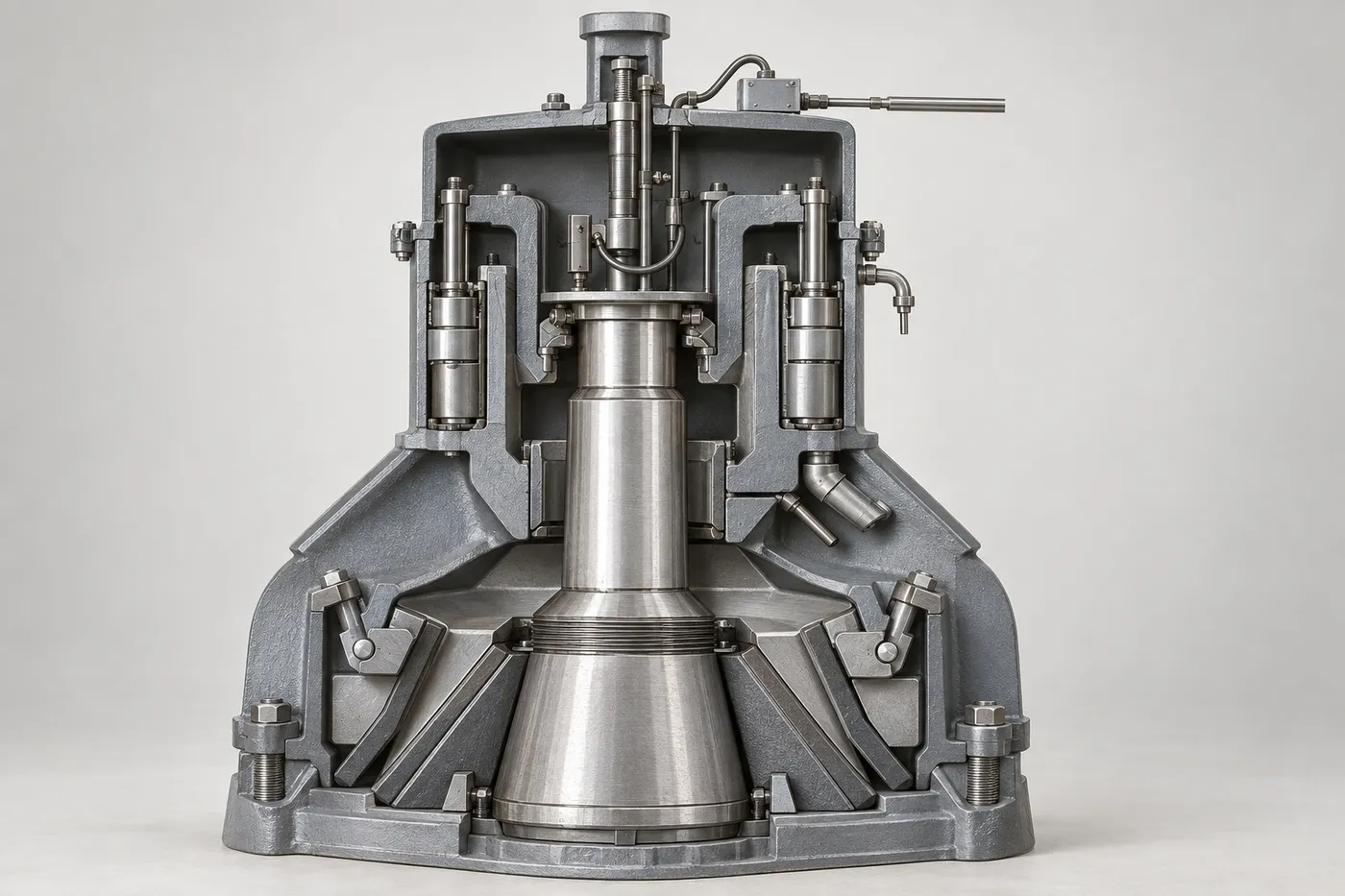
Select a model to jump to its component table; former and renamed designations are listed under “Historical names / renamings”.
| Model | Historical names / renamings | Period | Components |
|---|---|---|---|
| KVS gyratory crusher | KVS; KVS 48in (1960Picton); KVS 20in (1960Picton); KVS No.49½ (1960Picton); KVS No.25½ (1960McGinnis & O’Connor); KVS 26½in (1960Frazer Duntile); KVS No.39 (1960Frazer Duntile) | 1961–1962 | 24 |
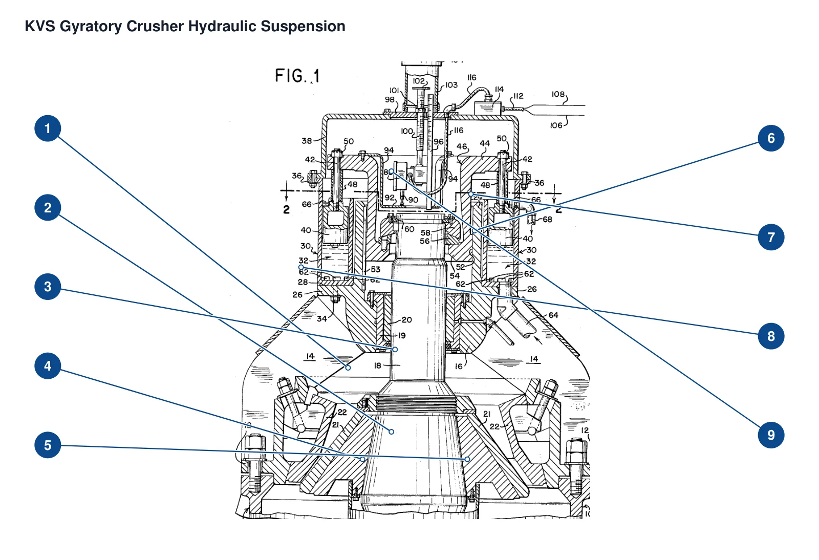
The numbers on the diagram correspond one to one with the rows below.
| No. | Component | Location | Applies to |
|---|---|---|---|
| 1 | Spider casting, arms and hub | Lower spider arm leading to the central hub | US3057563 technical design embodiment; commercial model not specified |
| 2 | Spider bushing assembly | Guide support where the upper main shaft passes through the hub | US3057563 technical design embodiment; commercial model not specified |
| 3 | Crusher main shaft | Central vertically suspended shaft | US3057563 technical design embodiment; commercial model not specified |
| 4 | Mantle | Visible lower conical face around the main shaft | US3057563 technical design embodiment; commercial model not specified |
| 5 | Bowl liner / Concave | Upper-shell working face opposite the mantle | US3057563 technical design embodiment; commercial model not specified |
| 6 | Suspension pistons and sealing rings | Vertical piston on the right of the annular casting | US3057563 technical design embodiment; commercial model not specified |
| 7 | Piston bolts, equal-length spacers and castle nuts | Connection between the piston and adjustment header | US3057563 technical design embodiment; commercial model not specified |
| 8 | Annular multiple-cylinder casting | Hydraulic-cylinder casting around the adjustment header | US3057563 technical design embodiment; commercial model not specified |
| 9 | Adjustment header and cap | Annular adjustment header above the suspended shaft | US3057563 technical design embodiment; commercial model not specified |
| Component |
|---|
| Frame casting |
| Anti-rotation key or spline |
| main shaft locking key ring |
| Oil supply and overflow channel/pipe set |
| Hydraulic oil storage tank |
| Hydraulic pump and drive motor |
| Oil supply solenoid valve |
| Piston type nitrogen accumulator |
| Pressure response solenoid valve |
| One-way valve |
| Pressure reducing valve and manual pressure relief valve group |
| Pressure switch/start/stop switch/junction box and cable housing |
| Spherical support ring/main shaft suspension ring |
| Position control switch and scale adjustment rod/screw handle |
| Control ring/switch bracket and protective cover |
Models with the same components are grouped together; select a group to open its component table.
| No. | Component | Location |
|---|---|---|
| 1 | Spider — Crossbeam casting and crossbeam arm/hub | Upper main shaft guide and suspension |
| 2 | Spider Bushing — Cross member bushing assembly | Upper end guide of main shaft in beam hub |
| 3 | Mainshaft — Crusher main shaft | Suspended crushing main shaft |
| 4 | Mantle — Moving cone crushing liner | Crushing surface under main shaft |
| 5 | Concaves — Fixed cone crushing liner | The crushing surface of the machine body relative to the moving cone |
| 6 | Suspension piston and sealing ring | Hydraulic support in multi-cylinder casting base |
| 7 | Piston connecting bolt/equal length spacer/castle nut | Piston to adjustment seat connection; dimensions not specified |
| 8 | Ring-shaped multi-cylinder casting base | Crossbeam top circumferential hydraulic cylinder block |
| 9 | Adjustment seat and top cover | Support main shaft and control switch |
| Frame casting | Crusher support frame | |
| Anti-rotation key or spline | Adjustment seat outer circle sliding guide | |
| main shaft locking key ring | main shaft ring groove suspension positioning | |
| Oil supply and overflow channel/pipe set | Multi-cylinder pressure equalization and oil return | |
| Hydraulic oil storage tank | Hydraulic supply system | |
| Hydraulic pump and drive motor | Hydraulic supply system | |
| Oil supply solenoid valve | Pump oil and cylinder supply switching | |
| Piston type nitrogen accumulator | Accept oil quantity when overloaded | |
| Pressure response solenoid valve | Accumulator branch | |
| One-way valve | Hydraulic oil supply branch | |
| Pressure reducing valve and manual pressure relief valve group | Oil return/emergency branch of oil storage tank | |
| Pressure switch/start/stop switch/junction box and cable housing | Hydraulic electronic control circuit | |
| Spherical support ring/main shaft suspension ring | Spherical seat suspension above the main shaft | |
| Position control switch and scale adjustment rod/screw handle | Setting the upper end position of the adjustment seat | |
| Control ring/switch bracket and protective cover | main shaft upper end suspension control |
The Gyratory crusher is also documented under these designations: KVS gyratory crusher, KVS, KVS 48in, KVS 20in, KVS No.49½, KVS No.25½, KVS 26½in, KVS No.39.
The Gyratory crusher is listed under the Kennedy Van Saun brand as: Gyratory crusher. Period: 1961–1962. Status: Historical model.
24 components are recorded, including: Frame casting, Spider, Spider Bushing, Mainshaft, Mantle, Concaves, Suspension piston and sealing ring, Piston connecting bolt/equal length spacer/castle nut and more. The full list with locations is in the components table on this page.
Model-specific components with their own page: Ring-shaped multi-cylinder casting base, Adjustment seat and top cover, Spherical support ring/main shaft suspension ring, Position control switch and scale adjustment rod/screw handle, Control ring/switch bracket and protective cover (5 in total).
Send us a drawing or sample and tell us the equipment model and part name.
Provide the equipment model, drawing for engineering review and quotation. If service life or wear is a concern, describe the operating conditions as well.
Or contact us directly: +86 156 3797 3199
zzx@anranst.com
ANRANST provides customers worldwide with engineering assessment, production at certified foundries to the customer technical requirements, quality control and finished-part delivery for custom wear parts and industrial spares, with scope to support other custom industrial parts.
We review mating surfaces and interface dimensions and assess material, heat treatment and manufacturing feasibility.
Material grades and heat-treatment processes are specified order by order, stated in the technical agreement and tracked through production.
Drawing confirmation, material and process control, production tracking, inspection and acceptance coordination.
We coordinate manufacturing, quality confirmation, packaging and delivery of complete finished parts in a workable, closed-loop supply process.
Provide the equipment brand, complete model and serial number, part name, part number or drawing number, drawing revision, quantity, material requirements and duty. If identifiers are unavailable, send photographs and key dimensions.
Submit an Enquiry