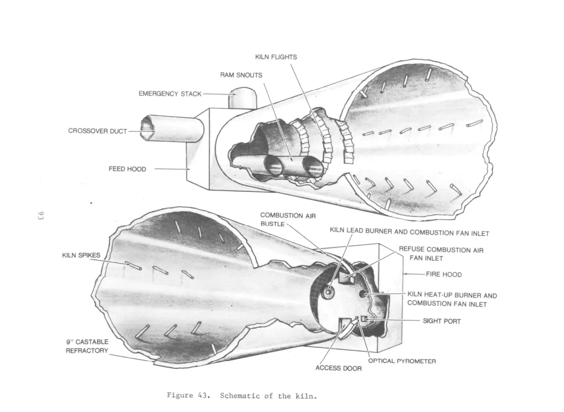
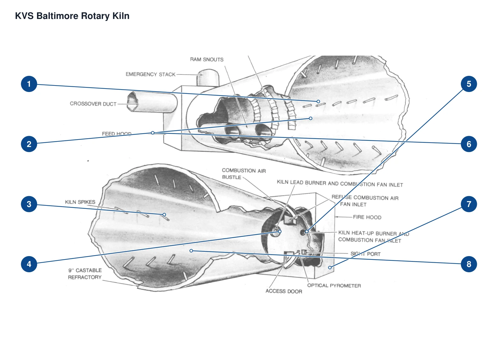
| 1 | kiln shell (Baltimore1979 case) | 6m×30.5m kiln main body; materials for the first 46cm of the feed end are different |
| 2 | Plate lifting parts flights (Baltimore) | The feed section starts from 0.5m and extends 5.6m; spiral arrangement |
| 3 | Tubular lifting parts spikes (Baltimore) | 6.3m post-processing section at the feed end, six rows |
| 4 | Annular air duct (Baltimore) | Discharge end seal circumferential air bustle |
| 5 | Burner (Baltimore) | |
| 6 | Kiln cover (Baltimore feed/discharge) | Stationary covers at both ends of the kiln shell |
| 7 | Optical pyrometer (Baltimore) | Leeds & Northrup, discharge end observation refractory; water-cooled |
| 8 | Refractory Lining — Fire Resistant Lining (Baltimore Zoning) | Distance along the feed end 0-30.5m; 23cm lining |
| Kiln shell | 2012 successor KVS coke calcining kiln body |
| Kiln Tyre / Riding Ring | 2012 successor KVS kiln bearing support |
| Kiln Inlet / Outlet Seal — Kiln head and kiln tail seal | 2012 subsequent calcination system interface |
| Refractory Lining | 2012 successor KVS kiln interior |
| Girth Gear / Bull Gear | 2012 successor KVS kiln driver |
| Pinion | 2012 successor KVS kiln driver |
| Reducer | 2012 successor KVS kiln driver |
| Variable speed motor | 2012 successor KVS kiln master driver |
| Auxiliary drive | 2012 successor KVS kiln driver |
| Burner | 2012 Coke calcination system heating |
| Y-shaped feed joint | 2012 Subsequent calcining kiln feeding outside the hood |
| Natural gas auxiliary burner (Merck No.50 example) | |
| Lined retaining angle steel (Baltimore) | Both ends of the kiln shell are used to fix refractory materials |
| Main motor (Baltimore) | Below the middle section of the kiln, 150hp |
| Water-cooled eddy current coupling/clutch (Baltimore) | Between main motor and Falk reducer |
| Water pressure protection switch (Baltimore) | Eddy current coupling cooling water, low pressure drive stop |
| Variable speed reducer (Baltimore) | Falk, connects the main drive and pinion gear, model name not specified |
| Pinion — Pinion (Baltimore) | The bottom of the middle section of the kiln meshes with the large ring gear |
| Girth Gear / Bull Gear — Large ring gear (Baltimore) | Kiln middle section circumferential direction |
| Girth Gear Guard — Gear rain seal cover (Baltimore) | Surrounding large and small gears |
| Splash lubrication system (Baltimore) | Large and small gears |
| Emergency gasoline engine drive (Baltimore) | Four-cylinder air-cooled spare, clutch PTO, electric starter and coupling |
| Support Roller / Carrying Roller — Support roller (Baltimore) | Two pairs, about 7.6m from each end; reported as trunnions |
| Kiln Tyre / Riding Ring — Tires (Baltimore) | There are two lanes around the kiln, connected to the supporting wheels. |
| Support roller bearing and water-cooled oil bath (Baltimore) | Each set of roller bearings, built-in cooling water pipe |
| Thrust Roller — Baltimore | Axial constraints of the wheel belt shown in Figure 47 and Table 19 |
| Thermocouple (Baltimore) | Kiln ends and kiln tail cover maintenance table 20 |
| Gas analyzer (Baltimore) | Feed cover O₂/CO₂ measurement |
| Variable air volume fan (Baltimore) | Discharge cover end inlet and annular air duct air supply |
| Bottom water seal (Baltimore) | Lower edge of feed cover and discharge cover |
| Kiln Inlet / Outlet Seal — Three-layer sealing of kiln shell and kiln cover (replaceable on site) | Circumferential connection of barrel cover after replacement of original steel labyrinth seal |
| Kiln Inlet / Outlet Seal — Original steel labyrinth seal (Baltimore original design) | Barrel cover connection; replaced on site due to thermal expansion gap problem |
| Emergency cover cylinder and solenoid valve (Baltimore) | Pneumatically opened emergency chimney cover; design suggestions are distinguished from installed status |
| Tire graphite lubrication block (Maintenance Table 19) | Tire lubrication, daily check supply in Table 19 |
| Nelson Kiln 1 Research Cottrell Multi-Cyclone Dust Collector | External parts of the kiln system; listed in declaration 1973, non-kiln internal parts |
| Nelson kiln 1 BoldEco bag dust collector | The kiln system is equipped with external equipment; it is listed in 2006 and is not called the original configuration in 1973. |
| Nelson kiln 2 Cyclo-Trell multi-cyclone dust collector | External parts of the kiln system; listed in declaration 1976, non-kiln internal parts |
| Nelson kiln 2 Amerex bag dust collector | The kiln system is equipped with external equipment; it is listed in 1998 and is not called the original configuration in 1976. |
| Nelson kiln 1 Ferenco contact cooler | External parts of the kiln system; listed in 1995, non-KVS kiln internal parts |
| Nelson kiln 2 KVS 20ft diameter contact cooler | The kiln system is equipped with external equipment; listed in 1976, only the on-site cooler specifications do not prove its independent commercial family/kiln shell internal structure |
| Bearing station assembly | 2012 successor KVS kiln support |
| Double wall cooling feed pipe | 2012 subsequent calcining kiln feed |
| Main combustion chamber (Merck No.50 example) | Main combustion section of rotary kiln |
| Secondary combustion chamber (Merck No.50 example) | Rotary kiln exhaust gas afterburner section, its manufacturer is not listed separately |
| Emergency bypass chimney (Merck No.50 example) | Before flue gas enters the control system, bypass occurs when abnormal shutdown occurs and overheating occurs. |
| Emergency chimney and counterweight cover (Baltimore) | Top of the feed cover; power outage/induced draft shutdown needs to be turned on |