
Mill lifters & pulp lifters
ألواح رفع المطحنة و رافعات اللب
Control grinding-media motion and pulp discharge separately
Shell lifter bars and pulp lifters both perform a lifting function, but they are different components. Shell lifter bars control the lift and trajectory of grinding media. Inner and outer pulp lifters belong to the grate discharge system, carrying pulp from behind the grates to the discharge cone or trunnion.
Shell lifting Shell liner systems for SAG, AG, ball and rod mills
Pulp discharge Inner and outer pulp lifters, discharge grates and discharge cones
Key performance requirements Profile retention, impact toughness, wear resistance, flow capacity and resistance to blockage
متطلبات التحديد Mill dimensions, discharge type, position, drawing reference, layout and operating conditions
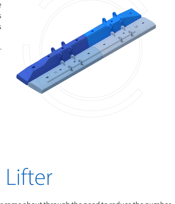
Functional distinction
تحديد الطاحونة OEM, complete model, diameter, effective length and structural version
وظيفة Shell lifting, inner pulp lifting, outer pulp lifting or ball mill pulp discharge
Structure Height, angle, pitch, hole positions, sectors, handedness and adjacent liners
ظروف التشغيل Speed, charge level, grinding media, ore, slurry, wear and blockage records
Lifting grinding media and transferring pulp are different functions
Shell lifter bars withstand repeated impacts from grinding media and ore and transfer motion to the mill charge. Excessive or insufficient profile height and uneven wear can change media trajectories, liner loads, power consumption and throughput.
Pulp lifters sit behind the discharge grates to reduce pulp retention and maintain steady discharge. They must match grate openings, the discharge cone, trunnion, rotation direction and discharge-end structure. Shape alone is insufficient for reproduction.
Product pages
Find the component by mill and installation position
Individual product pages maintain confirmed OEM drawing references, part numbers, standard models and material records.
SAG and AG mill shell lifter bars
Alternate or combine with shell liners. Check lifting height, leading face, arrangement, and impacts from steel balls and large ore pieces.
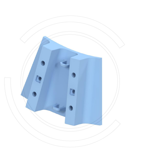
SAG mill inner pulp lifters
Sit in the inner part of the discharge system and receive pulp passing through the grates. Check sectors, flow channels, rotation direction, grate openings and discharge-cone interfaces.
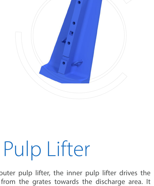
SAG mill outer pulp lifters
Connect the outer grate zone to downstream discharge channels. Check inner and outer ring positions, sector orientation, adjacent parts and the flow cross-section after wear.
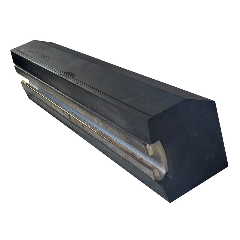
Ball mill lifter bars and plates
Work with shell liners to lift steel balls and material. Check mill dimensions, liner arrangement, media size, speed and feed and discharge types.
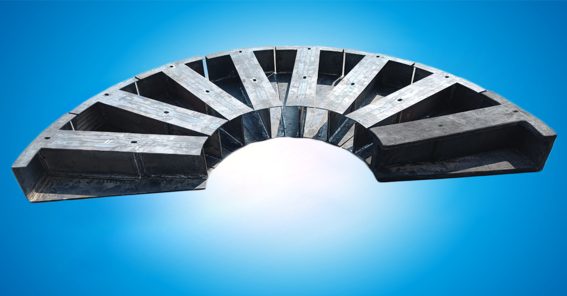
Ball mill pulp lifters
Transfer pulp in grate-discharge ball mills. Check the grates, discharge sectors, centre cone, trunnion and required flow capacity.
Rod mill lifter bars
Provide controlled lifting of steel rods while avoiding abnormal rod tangling and local impact. Check wave or bar profiles, rod specifications, shell layout and end transitions.
Materials and structure
Control profile retention, impact cushioning and flow performance separately
Different positions may use metal, rubber or composite structures. Final selection follows drawings, operating conditions and the complete liner design.
Failure diagnosis
Use profile, fracture and discharge condition to identify the cause
Abnormal lifter wear often involves the liner profile, mill operation and adjacent liners together.
| Symptoms | الفحوصات ذات الأولوية | Impacts |
|---|---|---|
| Rapid wear of the leading face | Ore and media impacts, lifting angle, speed, layout, material and heat treatment | Changed media trajectories and fluctuations in throughput and power |
| Lifter bar fracture or breakage | Toughness, section geometry, casting defects, support, fastening, foreign objects and abnormal impact | Overloading of adjacent liners and risk of shell damage |
| Rubber tearing or loose metal inserts | Composite interfaces, sharp foreign objects, insert support, fastening and adjacent component heights | Loss of profile and foreign material entering the mill charge |
| Reduced discharge capacity | Blocked grate openings, lifter channels, rotation direction, slurry viscosity, pulp pool and discharge cone | Pulp retention and abnormal power consumption or throughput |
| Local erosion of pulp lifters | Channel bends, gaps, reversed installation, grate layout, materials and inner-to-outer ring transitions | Slurry leakage, uneven flow and shorter replacement intervals |
| Loose bolts or slurry leakage | Hole positions, contact faces, preload, washers, rubber settlement and reinspection procedures | Liner movement, hole damage and safety risks |
Enquiry information
Confirming lifter bar and pulp lifter supply
Define manufacturing and acceptance requirements through complete mill identification, liner layout and position numbers.
Mill and discharge type
OEM, complete model, diameter, effective length, rotation direction, overflow or grate discharge, and structural version.
Position and layout
Shell rows, inner and outer discharge sectors, handedness or rotation direction, adjacent liners, grates and discharge cone.
مراجع الرسم والهندسة
OEM drawing and part numbers, layout drawings, hole positions, pitch, height, angle, flow channels and measurements of used parts.
ظروف التشغيل
Speed, charge level, steel balls or rods, ore size, slurry, throughput and discharge abnormalities.
المواد والتصنيع
Metal grade and heat treatment, rubber compound, inserts, composite interfaces, fastening and inspection requirements.
Wear and objectives
Wear measurements by row, fracture, tearing or blockage records, service life, maintenance windows and complete-set replacement strategy.
Technical references: Metso mill liner information treats lifter bars, head plates, shell plates, grates and the discharge system as an interconnected liner system. Metal, rubber and Poly-Met structures are combined to suit specific mill operating conditions.Metso Mill Liners · Metso Mill Lining Solutions
الأجزاء والمعدات ذات الصلة
Related mills, OEM series, products and materials
OEM and general equipment routes lead to the same product page, avoiding duplicate pages and conflicting data.
SAG and AG mills Shell lifting, grate discharge and inner and outer pulp lifter systems. Ball Mills Shell lifter bars and pulp lifters for grate-discharge mills. Industrial liners and wear linings System relationships between lifter bars, head liners, shell liners and discharge grates. العلامات التجارية والموديلات الأصلية Check layouts, drawing references and spare part numbers by brand, series and complete model.
Request identification and a quotation for lifter bars and pulp lifters
Submit mill models, dimensions, discharge type, positions, drawing references, layout drawings, current materials and wear records for technical review.
خدمات صنع في الصين
من التقييم الفني إلى تسليم المنتج بالكامل
توفر شركة ANRANST للعملاء العالميين تقييمات هندسية، واختيار التصنيع الصيني، ومراقبة الجودة، وتسليم الأجزاء النهائية لقطع الغيار الصناعية المقاومة للتآكل حسب الطلب، ويمكنها أيضًا دعم قطع الغيار الصناعية الأخرى حسب الطلب.
مراجعة الرسومات والهندسة
قم بمراجعة أسطح التزاوج وأبعاد الواجهة، وقم بتقييم جدوى المواد والمعالجة الحرارية والتصنيع.
تحديد المادة والمعالجة الحرارية
تُحدَّد درجات المواد وعمليات المعالجة الحرارية لكل طلب على حدة، وتُثبَّت في الاتفاقية الفنية وتُتابَع أثناء الإنتاج.
ضبط الجودة
يشمل ذلك تأكيد الرسم، ومراقبة المواد والعمليات، وتتبع الإنتاج، وتنسيق عمليات الفحص والقبول.
تسليم المنتج النهائي
تنظيم عمليات التصنيع والتحقق من الجودة والتعبئة والتغليف وتسليم المنتجات النهائية الكاملة لتشكيل حلقة إمداد قابلة للتنفيذ.
قم بتزويدنا بالنماذج الحالية، والرسومات، وأرقام الرسومات، وأرقام الأجزاء، والمواد، أو معلومات ظروف التشغيل، وسنقوم بتحديد التحقق الفني ومسار التوريد وفقًا لذلك.
إرسال طلب