
thyssenkrupp MULTIROK Vertical Shaft Impact Crushers

Identify MULTIROK 7 and MULTIROK 9 DUO specifications, rotor configurations, chamber wear parts and drive spares using thyssenkrupp technical data for legacy installations.

Legacy Installations and Part Configurations

Identify spares by model, rotor and crushing chamber

MULTIROK 7 and MULTIROK 9 DUO can use open or closed rotors with an anvil ring or an autogenous material bed. Part selection requires the full model, serial number, rotor and chamber configuration. The operating data below support machine identification and are not part manufacturing dimensions.

MULTIROK 7 Legacy Single-Motor Model
MULTIROK 9 DUO Legacy Twin-Motor Model
Open / Closed Rotor Check material and installed configuration
2022 Former TK Mining Business Acquired by FLS
Historical OEM Specifications

MULTIROK 7 and MULTIROK 9 DUO

These values identify the machine and narrow the parts search. Actual operating values depend on the duty and material properties; they must not be used as part manufacturing dimensions.

ModelCapacity: Open / Closed RotorMaximum Feed Size and Rotor DiameterDrive and Machine Identification
MULTIROK 7120–200 / 100–160 t/hMaximum feed 75 / 38 mm; rotor diameter 812 / 685 mmV-belt drive, 160 kW; 20 anvils with an anvil ring; total weight excluding motor: up to 5.7 t with anvil ring, up to 4.9 t with material bed
MULTIROK 9 DUO250–400 / 180–300 t/hMaximum feed 125 / 63 mm; rotor diameter 965 / 889 mmV-belt drive, 2 × 200 kW; 18 anvils with an anvil ring; total weight excluding motor: up to 11.0 t with anvil ring, up to 10.0 t with material bed
For capacity, maximum feed and rotor diameter, values before and after the slash refer to open and closed rotors respectively. Weight is distinguished by anvil ring or material bed configuration. Also check the serial number, rotor type, chamber, drawing revision and site modifications.
thyssenkrupp

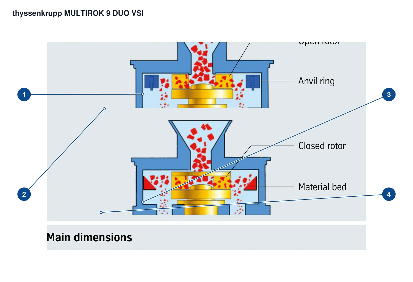
Component Location Diagram

The numbers on the diagram correspond one to one with the rows below.

thyssenkrupp MULTIROK Vertical Shaft Impact Crushers – Component Location Diagram
Pictured model: MULTIROK 9 DUO: upper image open rotor, lower image closed rotor
No.ComponentLocationApplies to
1Open rotorCentral rotor in the upper operating-mode viewMULTIROK 9 DUO: upper image open rotor, lower image closed rotor
2Anvil ringImpact ring around the open rotorMULTIROK 9 DUO: upper image open rotor, lower image closed rotor
3Closed rotorCentral rotor in the lower operating-mode viewMULTIROK 9 DUO: upper image open rotor, lower image closed rotor
4Material bedRock bed around the closed rotorMULTIROK 9 DUO: upper image open rotor, lower image closed rotor
Wear Parts and Mechanical Spares

Identify rotor, chamber and drive parts separately

The equipment design includes replaceable carbide rotor tips, an anvil ring or material bed, chamber wear plates, heavy-duty spherical roller bearings and a V-belt drive. Part numbers, materials and dimensions must match the installed machine drawings.

01

Open / Closed Rotors and Rotor Tips

Rotor & Carbide Tips

Check rotor type, diameter, rotation direction, carbide tip positions, retention design and old part markings. Specify model details and material grades from the installed machine drawings.

View Rotor Tip Details →
02

Anvil Rings, Anvils and Material Beds

Anvil Ring, Anvils & Material Bed

The chamber can use an anvil ring or an autogenous material bed. Check anvil count, ring segments, chamber dimensions, mounting and wear profile; wear parts for these configurations are not interchangeable.

View Anvil Ring Assembly Details →
03

Crushing Chamber Wear Plates

Crushing Chamber Wear Plates

Identify upper, lower and outer wear plate positions, left and right orientation, hole patterns, thickness and adjacent interfaces. Specify material properties from the drawing, feed abrasiveness and failure history.

View Wear Plate Details →
04

Bearing Pedestals, Pulleys and V-Belts

Bearing Pedestal & V-Belt Drive

The bearing pedestal uses heavy-duty spherical roller bearings with a V-belt drive. Confirm bearing designation, clearance, lubrication, pulley groove profile, diameter, bore and matched belt set against the installed machine.

View Bearing Pedestal Details →
FAQ

Frequently asked questions

How do I identify a MULTIROK model and configuration?

Provide the complete nameplate, serial number and machine records, then identify the rotor and crushing chamber configuration of the MULTIROK 7 or MULTIROK 9 DUO.

Is the model alone enough to specify rotor tips and liners?

No. Identify the open or closed rotor, anvil ring or material bed, serial number, rotor and chamber drawings, old part markings and actual dimensions.

Why is this listed as a legacy installation?

MULTIROK appears in thyssenkrupp Industrial Solutions historical product literature. The former TK Mining business joined FLS in 2022; identify parts using the original nameplate and subsequent business history.

Send the MULTIROK Nameplate, Configuration, Drawings or Old Parts

Please provide the full model, serial number, open or closed rotor, anvil ring or material bed configuration, drawing, old part photographs, key dimensions, feed material and failure details.

Equipment Brand and ModelDrawingDrawing or DimensionsCurrent MaterialPhotographs of Failed PartsTarget Service LifeOperating Conditions
Request a Quote

Or contact us directly: +86 156 3797 3199
zzx@anranst.com

Manufacturing Services in China

From Technical Assessment to Finished-Part Delivery

ANRANST provides customers worldwide with engineering assessment, production at certified foundries to the customer technical requirements, quality control and finished-part delivery for custom wear parts and industrial spares, with scope to support other custom industrial parts.

01

Drawing and Engineering Review

We review mating surfaces and interface dimensions and assess material, heat treatment and manufacturing feasibility.

02

Material and Heat-Treatment Specification

Material grades and heat-treatment processes are specified order by order, stated in the technical agreement and tracked through production.

03

Quality Control

Drawing confirmation, material and process control, production tracking, inspection and acceptance coordination.

04

Finished-Part Delivery

We coordinate manufacturing, quality confirmation, packaging and delivery of complete finished parts in a workable, closed-loop supply process.

Provide the existing model, drawings, drawing, materials or operating conditions so we can identify the appropriate technical review and supply route.

Submit an Enquiry