FLS VXPmill: طواحين التحريك القرصية المعيارية وقطع غيارها الأساسية

Use the mill design and documented installed model to identify discs, spacers, polyurethane liners, media retention screens, vertical shafts, bearings, drive parts, materials, drawing references and maintenance tooling.

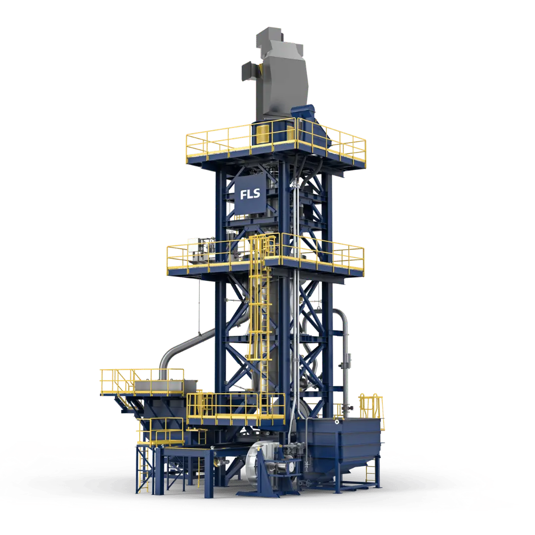
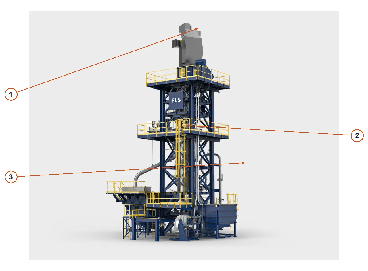
Manufacturer side-view rendering of the FLS VXPmill
Side view of the VXPmill from FLS's current website, showing the top-mounted drive, vertical grinding chamber, platform and lower piping.
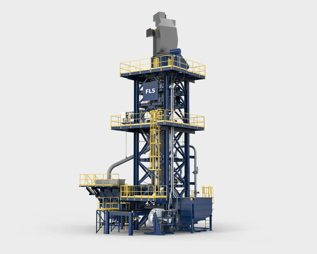
Manufacturer front-view rendering of the FLS VXPmill
Front view of the VXPmill from FLS's current website, showing the grinding chamber, drive frame, maintenance platform and external connections.
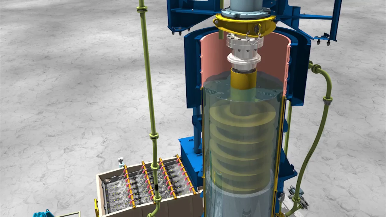
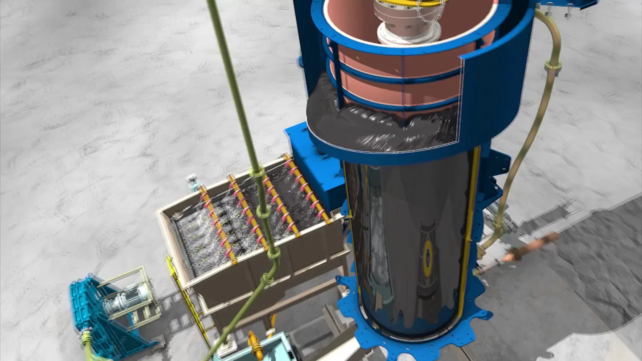
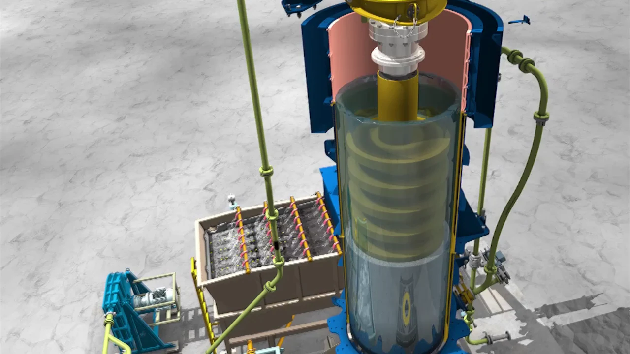
Disc stack and grinding chamber in the FLS VXPmill maintenance video
Frame from FLS's maintenance video: the open chamber reveals the modular disc stack, distinguishing this design from a screw-type tower mill.
OEM equipment guide

Distinguish the Disc-Type VXPmill from Screw-Type Tower Mills

The VXPmill uses a modular agitator shaft with removable discs and spacers. Slurry enters at the bottom, flows upward through the chamber and overflows through the upper media retention screen. This guide covers wear parts, other spares, drawing identification and maintenance tooling.

3 Current and installed-model entries
5 Grinding-chamber wear and contact parts
4 Shaft-system and structural spares
2 Manufacturer maintenance systems
Models and Key Dimensions

Current Product Family and Documented Installed Models

FLS's current website does not publish a complete standard model table suitable for ordering spares directly. This table lists only traceable current families and installed models; missing dimensions are not inferred.

Series / modelPublished identification informationالأبعاد الرئيسية / capacityStatusSpare-part confirmation limits
Current VXPmill familyDisc count, spacing, media charge and speed are tailored to the fine-grinding dutyTypical product size below 30 μm; no universal dimensional table is published on the current websiteCurrent seriesNameplate, serial number, full configuration, chamber general arrangement and disc layout
VXP2500FLS's Kibali installation publication identifies this modelThe installation publication does not give a universal diameter or length for spare-part orderingDocumented installed modelConfirm against the project nameplate, shaft system, disc count, spacers and screen drawings
VXP10000VXP mill package recorded in public project documentationMill internal diameter 1.90 m; effective length 5.07 m; installed power 3.0 MWProject-documented modelThese dimensions apply only to that project record, not to every VXP10000 installation
Wear parts

Discs, Spacers, Polyurethane Chamber Liners and Media Retention Screens

Follow the slurry path from the bottom inlet, through the disc-agitated grinding media, upward through the chamber and out through the top overflow.

Modular Agitator Discs — design and position in the FLS VXPmill
01

Modular Agitator Discs

Modular Impeller Disc

Discs are stacked along the vertical shaft to agitate the ceramic grinding media and form the VXPmill's main working elements. Confirm the full model, disc outside diameter and thickness, hole pattern, hub interface, installation height, disc count, spacing and rotation direction.

Material and manufacturing checks: FLS describes the discs as solid polyurethane. Confirm formulation, hardness, hub design and molding process against the original part, drawing number and operating conditions.

View the component guide →
Agitator Disc Spacers — design and position in the FLS VXPmill
02

Agitator Disc Spacers

Impeller Disc Spacer

Spacers set disc axial positions and energy distribution within the chamber. Check inside and outside diameters, length, end faces, registers, keyed or splined and fastening interfaces, disc assembly order and axial clamping method.

Material and manufacturing checks: Published information confirms removable modules but does not specify spacer materials for every installation. Confirm material, surface requirements and fits from drawings or the actual part.

View the component guide →
Polyurethane Grinding-Chamber Liners — design and position in the FLS VXPmill
03

Polyurethane Grinding-Chamber Liners

Grinding Chamber Polyurethane Lining

Protects the vertical chamber and slurry-contact surfaces from continuous abrasion by fine slurry and ceramic media. Confirm shell inside diameter, lining thickness and zones, connections, flanges, inlet and outlet openings, and on-site repair limits.

Material and manufacturing checks: FLS states that VXPmill slurry-contact parts are polyurethane-lined. Confirm formulation, hardness, bonding or mechanical attachment and repair process for the installed mill.

View the component guide →
Upper Media Retention Screen — design and position in the FLS VXPmill
04

Upper Media Retention Screen

Media Retention Screen

Located in the upper overflow zone, the screen releases ground slurry while retaining ceramic media. Check aperture size, open area, outside diameter, height, segmented design, attachment and clearance above the top disc.

Material and manufacturing checks: FLS's current product page specifies a polyurethane media retention screen. Confirm apertures, supports and material condition against target product size, media size and drawings.

View the component guide →
Bottom Feed and Media-Discharge Liners — design and position in the FLS VXPmill
05

Bottom Feed and Media-Discharge Liners

Bottom Feed and Media-Drain Linings

Bottom feed and media-discharge passages connect to the chamber. During maintenance, ceramic media drain through the bottom valve into a temporary storage tank. Check passage profile, flanges, valve seat, lining, closure element and chamber interface.

Material and manufacturing checks: Confirm polyurethane, engineering elastomers and matching valve-seat materials for liners contacting slurry or media. Do not substitute a conventional tower-mill feed-liner drawing number.

View the component guide →
Spare parts

Agitator Shafts, Hubs, Bearing Supports, Drive Connections and Bottom Valves

Check drive and structural parts separately. Where material or part numbers are unpublished, do not infer them; confirm against the nameplate, BOM, drawings, used parts and installed dimensions.

Agitator Shafts, Hubs and Axial Fasteners — design and position in the FLS VXPmill
01

Agitator Shafts, Hubs and Axial Fasteners

Impeller Shaft, Hubs and Axial Fasteners

Transmit drive torque and locate discs and spacers. Check shaft length and diameter, bearing seats, coupling end, hubs, keys or splines, threads, axial preload, coaxiality, dynamic balance and non-destructive testing requirements.

Material and manufacturing checks: Do not infer shaft material from appearance. Drive alloy steels are the usual starting family; confirm the final grade, heat treatment, mechanical properties and surface requirements from the drawing.

View the component guide →
Upper Bearings and Support Assemblies — design and position in the FLS VXPmill
02

Upper Bearings and Support Assemblies

Upper Bearing and Support Assembly

Support the vertical shaft and maintain disc-to-chamber clearance. Confirm bearing designation, clearance, shaft and housing fits, lubrication, end covers, seals, supports, loads and locating interfaces with the drive frame.

Material and manufacturing checks: Confirm bearings, housings, fasteners and lubricants against original designations, load, speed, temperature rise and accuracy requirements.

View the component guide →
Motor, Coupling and Drive-Frame Connections — design and position in the FLS VXPmill
03

Motor, Coupling and Drive-Frame Connections

Motor, Coupling and Drive-Frame Components

The top-mounted drive supplies torque to the vertical shaft. Confirm motor power and speed, variable-frequency configuration, coupling type, bore, keys, fasteners, guards, installation height and drive-frame hole pattern.

Material and manufacturing checks: Confirm couplings, bushings, connecting shafts and fasteners by torque, fatigue, alignment, fits and original material. Do not assume generic gearbox parts fit the VXPmill.

View the component guide →
Bottom Valves, Flanges and Seal Assemblies — design and position in the FLS VXPmill
04

Bottom Valves, Flanges and Seal Assemblies

Bottom Valve, Flange and Sealing Components

Used for operational isolation, chamber flushing and media discharge during maintenance. Confirm valve type, bore, pressure, flanges, seat, lining, actuator, interlocks and temporary-tank piping.

Material and manufacturing checks: Confirm valve-body, seat, elastomer and fastener materials against the slurry, ceramic media, corrosion, pressure and site cleaning fluids.

View the component guide →
Maintenance Tooling

Disc Service Tables, Lifting Tools and Media Discharge/Storage Systems

The following systems are shown in FLS's VXPmill maintenance video or current product page. Images and descriptions apply specifically to VXPmill maintenance.

Disc service table and lifting tools in the FLS VXPmill maintenance animation
01

Disc Service Table and Lifting Tools

Disc Maintenance Table and Lifting Tool

FLS's maintenance video shows disc removal, positioning and lifting on a dedicated service table. Design tooling for disc diameter, weight, lifting points, working height, rails or table surface, locking arrangements and available site space.

Watch the FLS maintenance video →
Media discharge and temporary storage system in the FLS VXPmill maintenance animation
02

Media Discharge and Temporary Storage System

Media Drain and Temporary Holding System

Before maintenance, flush the mill and open the bottom valve to drain ceramic media into a temporary tank, clearing space for disc servicing. Confirm tank volume, valves, screening, pumping, piping and the media return route.

Watch the FLS maintenance video →
Materials and Failure Modes

Polyurethane for Slurry Contact; Shaft Materials Selected for Torque and Fatigue

Polyurethane is the principal material family for discs, chamber liners and the upper media retention screen. Formulation, hardness, hydrolysis and wear resistance, bonding and dimensional stability must match the grinding media, slurry, temperature, speed and installed design.

Drawing and Spare-Part Numbers

Match Disc, Spacer and Shaft References to the Actual Disc Layout

With any reference number, provide the full model, serial number, disc layout, disc count and spacing, hub/shaft interface, screen aperture, chamber dimensions, used-part photographs, material, grinding media and wear records.

Are VXPmill and screw-type tower-mill parts interchangeable?

No. VXPmill has a modular disc-and-spacer agitator shaft, while screw-type tower mills such as FTM use a screw agitator. Confirm models, shaft systems, chambers, screens, interfaces and tooling separately.

Why are additional dimensions not listed?

FLS's current website does not publish a complete standard dimensional table for direct spare-part ordering. We list only traceable current families and documented installations. Confirm other installations by nameplate, drawings and serial number.

Send Your FLS VXPmill Model and Disc, Spacer, Liner or Shaft Requirements

Provide the full model, serial number, OEM or third-party reference, disc layout, disc and spacer dimensions, hub/shaft interfaces, chamber and screen drawings, materials, grinding media, speed, slurry and wear records. These support identification, material assessment, manufacturing coordination, quality control and finished-part delivery.

Send details for a quotation

رقم الهاتف: +86 156 3797 3199
zzx@anranst.com

خدمات صنع في الصين

من التقييم الفني إلى تسليم المنتج بالكامل

توفر شركة ANRANST للعملاء العالميين تقييمات هندسية، واختيار التصنيع الصيني، ومراقبة الجودة، وتسليم الأجزاء النهائية لقطع الغيار الصناعية المقاومة للتآكل حسب الطلب، ويمكنها أيضًا دعم قطع الغيار الصناعية الأخرى حسب الطلب.

01

مراجعة الرسومات والهندسة

قم بمراجعة أسطح التزاوج وأبعاد الواجهة، وقم بتقييم جدوى المواد والمعالجة الحرارية والتصنيع.

02

تحديد المادة والمعالجة الحرارية

تُحدَّد درجات المواد وعمليات المعالجة الحرارية لكل طلب على حدة، وتُثبَّت في الاتفاقية الفنية وتُتابَع أثناء الإنتاج.

03

ضبط الجودة

يشمل ذلك تأكيد الرسم، ومراقبة المواد والعمليات، وتتبع الإنتاج، وتنسيق عمليات الفحص والقبول.

04

تسليم المنتج النهائي

تنظيم عمليات التصنيع والتحقق من الجودة والتعبئة والتغليف وتسليم المنتجات النهائية الكاملة لتشكيل حلقة إمداد قابلة للتنفيذ.

قم بتزويدنا بالنماذج الحالية، والرسومات، وأرقام الرسومات، وأرقام الأجزاء، والمواد، أو معلومات ظروف التشغيل، وسنقوم بتحديد التحقق الفني ومسار التوريد وفقًا لذلك.

إرسال طلب