
What other names or designations is the Rod mill known by?
The Rod mill is also documented under these designations: Hardinge Rod Mill, Hardinge Rod Rod mill, Hardinge Universal Rod Mill.
Rod mill · 1939 · 1 model
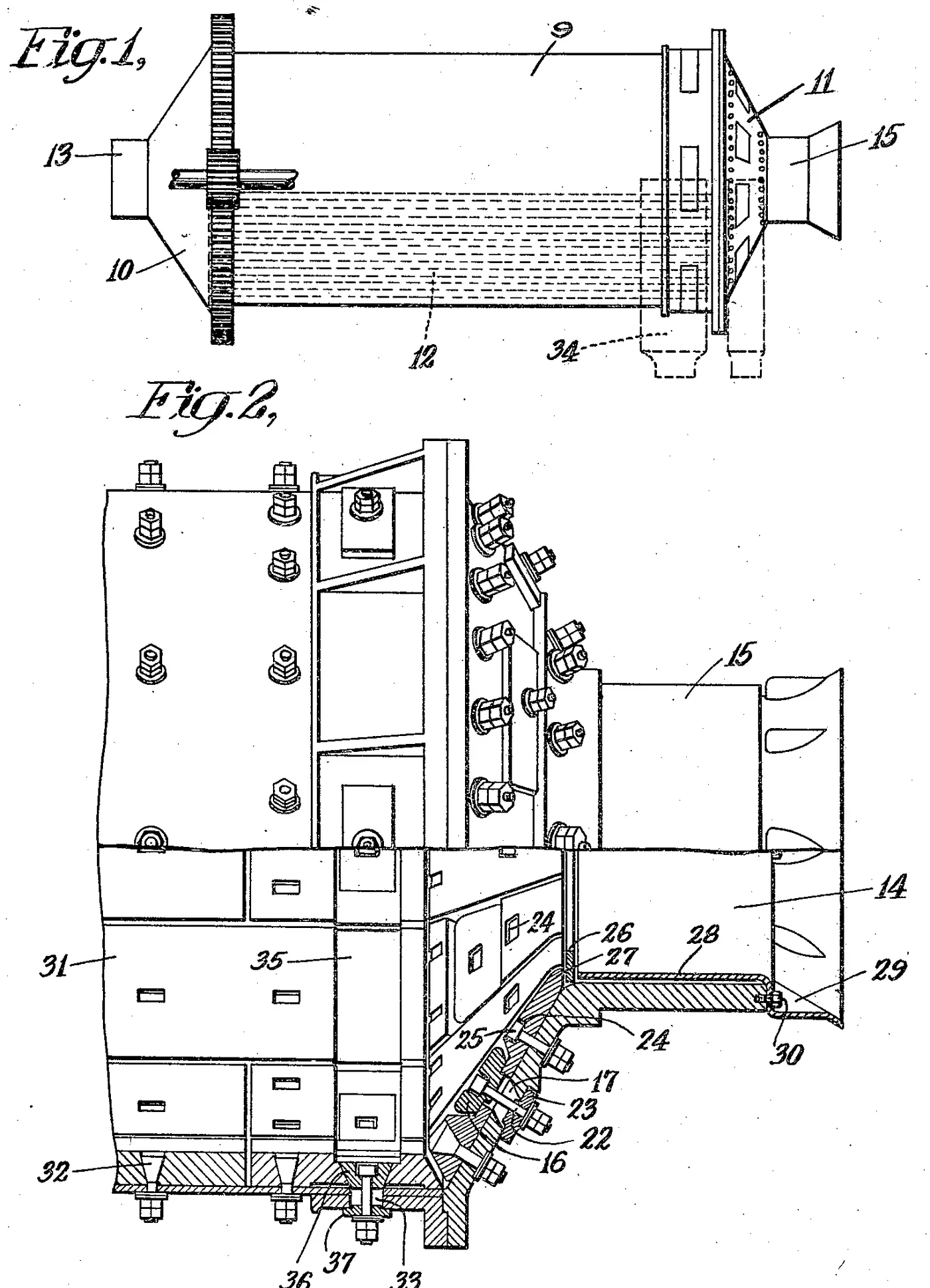
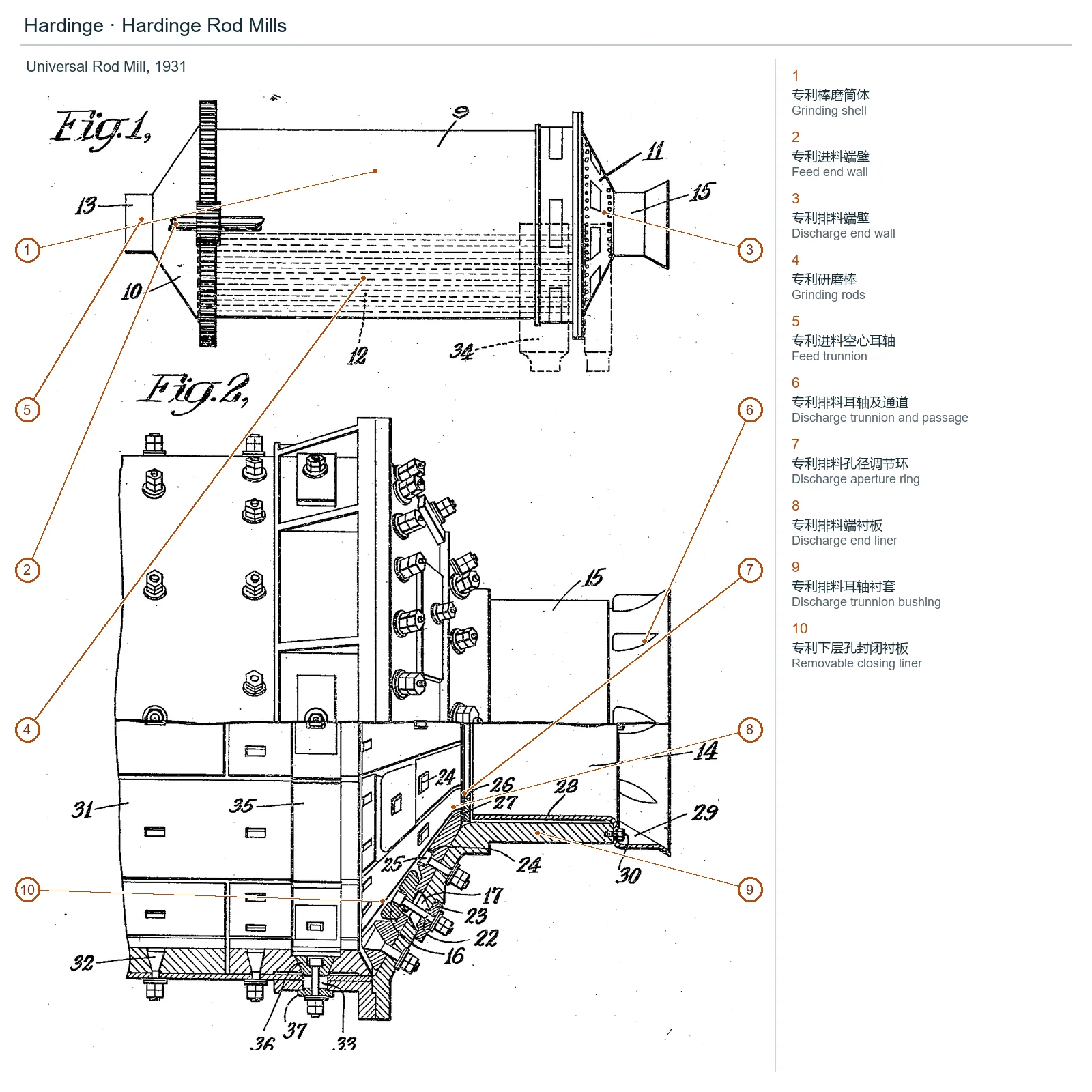
Select a model to jump to its component table; former and renamed designations are listed under “Historical names / renamings”.
| Model | Historical names / renamings | Period | Components |
|---|---|---|---|
| Hardinge Rod Mill | Hardinge Rod Rod mill; Hardinge Universal Rod Mill | 1939 | 22 |
The numbers on the diagram correspond one to one with the rows below.
| No. | Component | Location | Applies to |
|---|---|---|---|
| 1 | Grinding shell | Visible grinding shell in Universal Rod Mill, 1931 | US1807034 Fig1/2 patented design |
| 2 | Feed end wall | Visible feed end wall in Universal Rod Mill, 1931 | US1807034 Fig1/2 patented design |
| 3 | Discharge end wall | Visible discharge end wall in Universal Rod Mill, 1931 | US1807034 Fig1/2 patented design |
| 4 | Grinding rods | Visible grinding rods in Universal Rod Mill, 1931 | US1807034 Fig1/2 patented design |
| 5 | Feed trunnion | Visible feed trunnion in Universal Rod Mill, 1931 | US1807034 Fig1/2 patented design |
| 6 | Discharge trunnion and passage | Visible discharge trunnion and passage in Universal Rod Mill, 1931 | US1807034 Fig1/2 patented design |
| 7 | Discharge aperture ring | Visible discharge aperture ring in Universal Rod Mill, 1931 | US1807034 Fig1/2 patented design |
| 8 | Discharge end liner | Visible discharge end liner in Universal Rod Mill, 1931 | US1807034 Fig1/2 patented design |
| 9 | Discharge trunnion bushing | Visible discharge trunnion bushing in Universal Rod Mill, 1931 | US1807034 Fig1/2 patented design |
| 10 | Removable closing liner | Visible removable closing liner in Universal Rod Mill, 1931 | US1807034 Fig1/2 patented design |
Models with the same components are grouped together; select a group to open its component table.
| No. | Component | Location |
|---|---|---|
| 1 | Patented rod grinding cylinder | Cylindrical grinding chamber |
| 2 | Patented rod mill feed end wall | Allows tapered or dished end walls; not all commercial machine structures |
| 3 | Patented rod grinding discharge end wall | Tapered/dish-shaped end with discharge holes of different radii |
| 4 | Grinding Rods / Steel Rods — Patented grinding rod | Cylindrical grinding chamber, the length is close to the internal length of the cylinder |
| 5 | Patented feed hollow trunnion | Feed end channel |
| 6 | Patented discharge trunnion and channel | Discharge end slurry channel |
| 7 | Patented discharge aperture adjustment ring | Trunnion discharge channel, equal outer diameter/different hole diameter replacement rings; non-commercial kit |
| 8 | Discharge End Liner — Patented discharge end liner | Edge of the liner against which the adjustment ring rests |
| 9 | Patented discharge trunnion bushing | Keep the adjusting ring and line the trunnion; the end is flared, and the original text mentions that the recess is not cast with alloy. |
| 10 | Patented lower hole removable closing liner | Discharge end wall, complete the inner surface when closed |
| Patented end wall sealing plate bolts and bridge plate | Lower hole closed liner fixed | |
| Patented upper hole sealing bolt | The upper end wall discharge hole can be detachably closed | |
| Patented Bushing Studs and Nuts | Maintain flared bushing, removable sleeve/replacement of adjusting ring; operating steps not transcribed | |
| Shell Liner / Shell Plate — Patented smooth cylinder liner (optional) | The picture shows a type of removable lining | |
| Shell Liner / Shell Plate — Patented circumferential rib shell liner (optional form) | The original text lists the ribbed lining separately, which is not regarded as standard together with the smooth type. | |
| Shell Liner / Shell Plate — Patented chute shell liner (direction variant) | Figure 3/4 Opposite chute, wet/dry and rotational effects are only according to the original design | |
| Patented shell liner fixing bolts | Removable lining fixed | |
| Patented discharge hole structure around the cylinder wall | Design below the rod end/near the discharge end, independent of the end wall hole | |
| Patented peripheral discharge hole sealing plate | Peripheral holes can be completely closed | |
| Patented peripheral sealing plate bridge plate and bolts | Peripheral hole fixing piece | |
| Patented perforated closing plate (optional) | Figure 5 uses perforated plate to change the effective discharge area | |
| Patented external return chute (optional as shown) | The one shown in Figure 1 is sent back to the grinding peripheral groove; do not pretend to be the standard configuration of the actual product. |
The Rod mill is also documented under these designations: Hardinge Rod Mill, Hardinge Rod Rod mill, Hardinge Universal Rod Mill.
The Rod mill is listed under the Hardinge brand as: Rod mill. Period: 1939. Status: Historical model.
22 components are recorded, including: Patented rod grinding cylinder, Patented rod mill feed end wall, Patented rod grinding discharge end wall, Grinding Rods / Steel Rods, Patented feed hollow trunnion, Patented discharge trunnion and channel, Patented lower hole removable closing liner, Patented end wall sealing plate bolts and bridge plate and more. The full list with locations is in the components table on this page.
Send us a drawing or sample and tell us the equipment model and part name.
Provide the equipment model, drawing for engineering review and quotation. If service life or wear is a concern, describe the operating conditions as well.
Or contact us directly: +86 156 3797 3199
zzx@anranst.com
ANRANST provides customers worldwide with engineering assessment, production at certified foundries to the customer technical requirements, quality control and finished-part delivery for custom wear parts and industrial spares, with scope to support other custom industrial parts.
We review mating surfaces and interface dimensions and assess material, heat treatment and manufacturing feasibility.
Material grades and heat-treatment processes are specified order by order, stated in the technical agreement and tracked through production.
Drawing confirmation, material and process control, production tracking, inspection and acceptance coordination.
We coordinate manufacturing, quality confirmation, packaging and delivery of complete finished parts in a workable, closed-loop supply process.
Provide the equipment brand, complete model and serial number, part name, part number or drawing number, drawing revision, quantity, material requirements and duty. If identifiers are unavailable, send photographs and key dimensions.
Submit an Enquiry