
ABON الكسارات المسننة منخفضة السرعة

Start with centre-sizing or side-sizing configurations to identify tooth segments, liners, scrapers, roll shafts, bearings, heavy-duty gearboxes and fluid couplings, then confirm materials and drawing references for quotation.

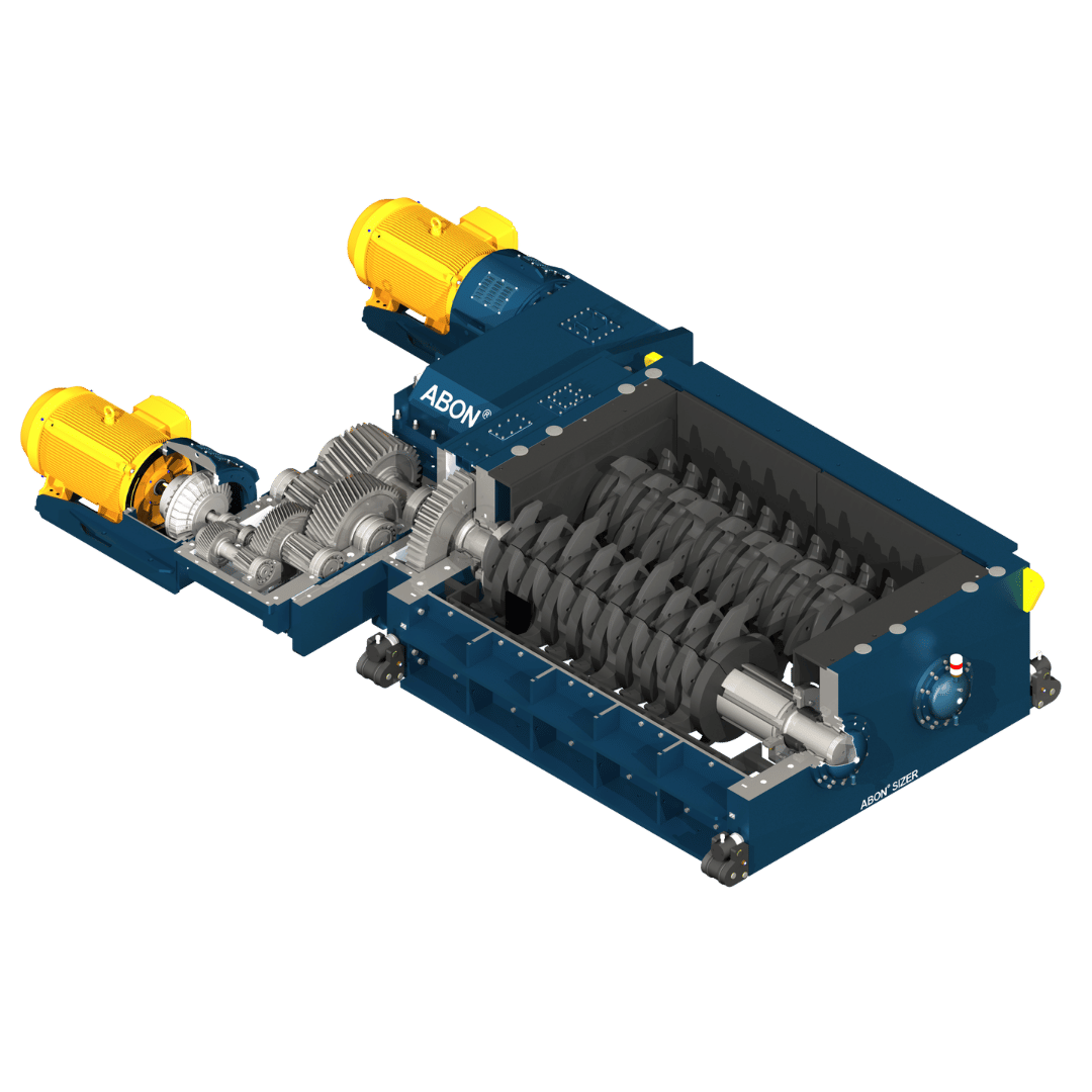
Official ABON low-speed sizer cutaway rendering
Official FLS ABON Sizer cutaway rendering showing tooth segments on both rolls, side-wall protection, drive gearboxes and roll-shaft supports.
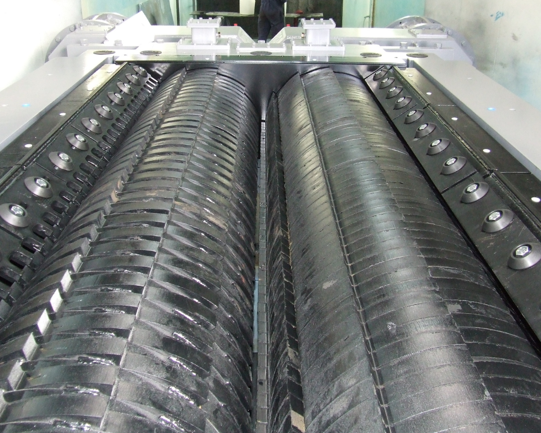
ABON low-speed sizer tooth segments and side liners
Official FLS photograph of tooth segments and side liners. Confirm centre or side sizing, tooth layout and tip clearances against the project configuration.
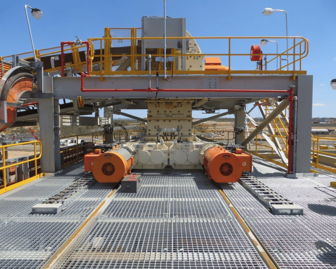
ABON low-speed sizer site installation
Official FLS installation photograph showing the low-profile body, twin drives and withdrawable maintenance arrangement for installation identification.
OEM equipment guide

Configurations, قطع الغيار المستهلكة and Drive Spares on One Page

ABON Sizers are engineered for the material, maximum feed, throughput and target product size. Key identification criteria are sizing method, shaft centres, roll length, drive arrangement and tooth-segment layout.

370–1,600 mm Published Shaft-Centre Range
500–4,200 mm Published Roll-Length Range
15–76 rpm Published Shaft-Speed Range
650+ Worldwide التركيبات Reported by FLS
Standard Configurations and Documented Models

Centre Sizing, Side Sizing and 16/400CHDTD-RA

The current range is defined by engineered configurations. The official brochure also documents the Extreme Duty 16/400CHDTD-RA project model.

Configuration / ModelSizing MethodMaximum Feed SizeMaximum ThroughputTypical Top Product SizeSpeedKey Configuration
Primary centre-sizing configurationCentre sizing / primaryUp to 1,600 mmUp to 14,000 tphTypically 250–350 mm0.8–1.2 m/sShaft centres 370–1,600 mm; roll length 500–4,200 mm
Secondary and tertiary side-sizing configurationSide sizing / secondary & tertiaryUp to 350 mmUp to 5,000 tphTypically 75–150 mmUp to approximately 1.8 m/sShaft centres 370–1,600 mm; roll length 500–4,200 mm
16/400CHDTD-RA Extreme DutyEngineered model documented in the official brochure1,600 mmOver 10,000 tphDefined by project tooth profiles and spacer ringsConfigured within a shaft-speed range of 15–76 rpmDocumented for extreme-duty projects up to approximately 500 MPa

Single, twin or four-drive arrangements, tooth profiles, spacer rings, product size and power are project-specific. Before manufacture, verify the nameplate, serial number, general arrangement, shaft drawings and tooth-segment layout.

Wear parts

Tooth Segments, Spacer Rings, Side and Bottom Liners, and Scrapers

Each position describes duty, candidate materials and dimensions requiring verification, with a link to the corresponding mineral-sizer component page.

ABON Sizer Tooth Segments — identification and installation position
01

Sizer Tooth Segments

Sizing Tooth Segments

Segments fit into machined shaft grooves; tooth profile, height and spacer rings together control nip and top product size. Check centre or side sizing, shaft centres, roll length, tooth layout, material hardness and wear records.

Material and manufacturing checks: Consider wear-resistant alloy steel, duty-validated special alloys or local hardfacing. Confirm composition, heat treatment and repair processes against project drawings.

View the Component Page →
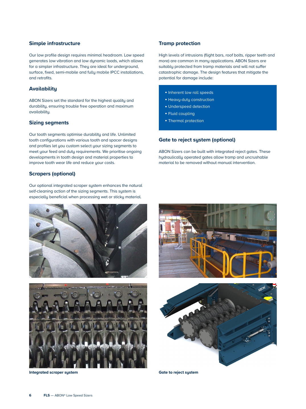
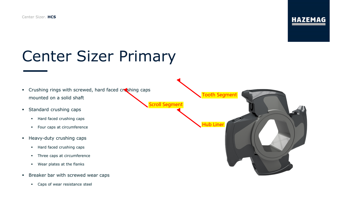
ABON Tooth-Segment Spacer Rings and Shims — identification and installation position
02

Tooth-Segment Spacer Rings and Shims

Tooth Spacers & Adjustment Shims

Together with segment layout, these set controlled gaps and top product size. Check shaft diameter, thickness combinations, keyways or locating features, sequence and axial retention.

Material and manufacturing checks: Use quenched and tempered alloy steel or wear-resistant steel confirmed by original drawings. Verify thickness tolerances, end-face parallelism and surface treatment against assembly requirements.

View the Component Page →
ABON البطانة الجانبية and End Plates — identification and installation position
03

البطانة الجانبية and End Plates

Side Liner & End Plate

Protect side walls and form part of the controlled side-sizing gap. Check centre or side design, installation zone, plate references, hole pattern, thickness and tooth-tip clearances.

Material and manufacturing checks: Select quenched and tempered wear plate, bimetallic plate or a duty-validated wear design according to impact and abrasion.

View the Component Page →
ABON Bottom Liners and Base Protection — identification and installation position
04

Bottom Liners and Base Protection

Bottom Liner & Base Plate

Protect the lower chamber and discharge area from fines erosion, rebounding material and local build-up wear. Check plate positions, curvature, holes, discharge clearances and maintenance access direction.

Material and manufacturing checks: Confirm quenched and tempered wear plate or bimetallic plate according to thickness, impact, welding and fastening method.

View the Component Page →
ABON Integrated Scrapers — identification and installation position
05

Integrated Scrapers

Integrated الكاشطة / المنظف

Optional scrapers assist natural tooth-segment self-cleaning with wet, sticky materials. Check scraper profile, dynamic clearance to segments, supports, adjustment travel and wear allowance.

Material and manufacturing checks: Select quenched and tempered wear plate, wear-resistant alloys or composite scrapers according to adhesion, abrasion and impact.

View the Component Page →
ABON Tooth-Segment Bolts and Locks — identification and installation position
06

Tooth-Segment Bolts and Locks

Tooth Segment Bolts & Fasteners

Secure tooth segments, spacer rings or related wear assemblies. Check thread size, strength class, length, head form, locking method, preload and assembly access.

Material and manufacturing checks: Confirm high-strength alloy steel, thread machining and heat treatment against load and fatigue conditions.

View the Component Page →
Spare parts

Roll Shafts, Bearings, Heavy-Duty Gearboxes and وصلات السوائل

Check drive and support parts by shaft centres, effective roll length, drive count, machine side, rotation, ratio, fits and lubrication.

ABON Sizer Roll-Shaft Assembly — identification and installation position
01

Sizer Roll-Shaft Assembly

Sizing Roll Shaft Assembly

Carries tooth segments and transmits high torque. Check shaft centres, effective roll length, diameters, end interfaces, keyways or splines, segment grooves, rotation and runout.

Material and manufacturing checks: Verify large alloy-steel forgings, heat treatment, machining accuracy and non-destructive testing against torque, impact and original drawings.

View the Component Page →
ABON Bearings and Housings — identification and installation position
02

Bearings and Housings

Bearing & غلاف المحمل

Support the roll shaft at drive and non-drive ends with integral oil-bath lubrication. Check machine side, bearing designation, housing bore, end covers, seals, oil level and sensor connections.

Material and manufacturing checks: Confirm bearing steel, cast-steel or ductile-iron housings and seal materials according to load, speed, lubrication and temperature rise.

View the Component Page →
ABON Heavy-Duty Gearboxes and Gear Drives — identification and installation position
03

Heavy-Duty Gearboxes and Gear Drives

Heavy-duty علبة التروس & Gearing

Convert motor power to low-speed, high-torque output. Check single, twin or four-drive configuration, ratio, input/output shafts, rotation, mounting surfaces, gear data and lubrication.

Material and manufacturing checks: Use carburised or quenched and tempered alloy-steel gears and forged shafts; verify accuracy, hardness, core toughness and contact patterns against drawings.

View the Component Page →
ABON وصلات السوائل — identification and installation position
04

وصلات السوائل

Fluid Coupling

Located between the motor and heavy-duty gearbox to cushion starting and overloads. Check size, transmitted power, speed, fluid charge, orientation, thermal protection and connection dimensions.

Material and manufacturing checks: Confirm alloy-steel drive parts, housing materials and oil-resistant seals according to power, temperature rise and working fluid.

View the Component Page →
Drawing and Spare-Part Numbers

Match OEM or Third-Party References to Installed Configuration and Position

Provide the complete nameplate, serial number, sizing method, shaft centres, roll length, drive arrangement, tooth layout, OEM/third-party references and used-part dimensions so that we can establish traceable matches.

How is an installed ABON Sizer configuration identified?

First establish centre or side sizing, then verify shaft centres, effective roll length, drive count, tooth-segment and spacer-ring layout, the complete nameplate and project drawings.

Can tooth segments be manufactured from photographs alone?

No. Tooth profile and height, mounting grooves, spacer rings, axial sequence, material hardness, impact and wear records must also be checked.

Why is there no dedicated tooling section?

The official FLS brochure states that tooth segments can be replaced without removing the roll shafts and that normal assembly and maintenance require no special tools. Unverified dedicated tooling is therefore not listed.

Send the ABON Sizer Nameplate, Tooth Layout or Drawings

Provide sizing method, shaft centres, roll length, drive count, OEM/third-party references, used-part photographs, material and duty. These support identification, material assessment, production at certified foundries, quality control and finished-part delivery.

Send التفاصيل for a Quotation

رقم الهاتف: +86 156 3797 3199
zzx@anranst.com

خدمات صنع في الصين

من التقييم الفني إلى تسليم المنتج بالكامل

توفر شركة ANRANST للعملاء العالميين تقييمات هندسية، واختيار التصنيع الصيني، ومراقبة الجودة، وتسليم الأجزاء النهائية لقطع الغيار الصناعية المقاومة للتآكل حسب الطلب، ويمكنها أيضًا دعم قطع الغيار الصناعية الأخرى حسب الطلب.

01

مراجعة الرسومات والهندسة

قم بمراجعة أسطح التزاوج وأبعاد الواجهة، وقم بتقييم جدوى المواد والمعالجة الحرارية والتصنيع.

02

تحديد المادة والمعالجة الحرارية

تُحدَّد درجات المواد وعمليات المعالجة الحرارية لكل طلب على حدة، وتُثبَّت في الاتفاقية الفنية وتُتابَع أثناء الإنتاج.

03

ضبط الجودة

يشمل ذلك تأكيد الرسم، ومراقبة المواد والعمليات، وتتبع الإنتاج، وتنسيق عمليات الفحص والقبول.

04

تسليم المنتج النهائي

تنظيم عمليات التصنيع والتحقق من الجودة والتعبئة والتغليف وتسليم المنتجات النهائية الكاملة لتشكيل حلقة إمداد قابلة للتنفيذ.

قم بتزويدنا بالنماذج الحالية، والرسومات، وأرقام الرسومات، وأرقام الأجزاء، والمواد، أو معلومات ظروف التشغيل، وسنقوم بتحديد التحقق الفني ومسار التوريد وفقًا لذلك.

إرسال طلب