Cone crusher

Cone crusher · 1928 · 3 models

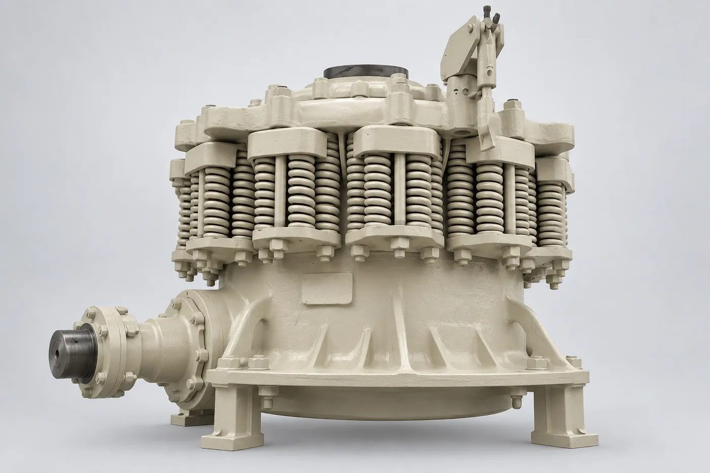
Symons Cone crusher – Cone crusher
Symons Cone crusher – Cone crusher (2)
Symons
SymonsBrand
Cone crusherEquipment type
1928Period
Historical modelStatus
Symons

Models and Historical Names in This Series

Select a model to jump to its component table; former and renamed designations are listed under “Historical names / renamings”.

ModelHistorical names / renamingsPeriodComponents
Symons Short Head cone crushersSymons Short Head 3; Symons Short-Head 24; Symons Short-Head 36; Symons Short-Head 48; Symons Short-Head 51; Symons Short-Head 60; Symons Short-Head 66; Symons Short-Head 84; Bergeaud-Symons 3ft tête courte / bol fin13
Symons Standard cone crushersSymons Standard 3; Symons Standard 4¼; Symons Standard 5½; Symons Standard 24; Symons Standard 36; Symons Standard 48; Symons Standard 51; Symons Standard 60; Symons Standard 66; Symons Standard 84; Symons Standard 10ft8
Symons cone crusher historical specifications overviewSymons Cone crusher 2; Symons Cone crusher 3; Symons Cone crusher 4¼; Symons Cone crusher 5½; Symons Cone crusher 7; Symons Cone crusher 5½ HD; Symons Cone crusher 7 HD; Symons Cone crusher 7 XHD; Symons Cone crusher 7 SHD; Symons Cone crusher 4; Symons Standard 10ft; Symons 7ft192832
Symons

Numbered Components

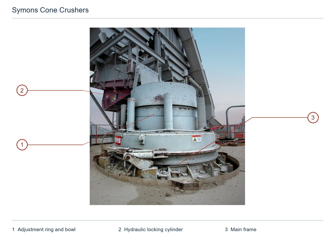
The numbers on the diagram correspond one to one with the rows below.

No.ComponentLocationApplies to
1Adjustment ring and bowlVisible bowl between hydraulic posts at centre, with adjustment ring below; grouped assemblySymons (Metso 2016 installed upgrade configuration; foot-size specification not specified)
2Hydraulic locking cylinderVertical hydraulic locking unit around bowlSymons (Metso 2016 installed upgrade configuration; foot-size specification not specified)
3Main frameLower load-bearing main frame beneath adjustment ringSymons (Metso 2016 installed upgrade configuration; foot-size specification not specified)
4MantleLiner on outer face of headSymons (FLS EXCEL design family; exact installed model, Standard/Short Head chamber and configuration not specified)
5Bowl LinerCrushing chamber liner inside bowlSymons (FLS EXCEL design family; exact installed model, Standard/Short Head chamber and configuration not specified)
6Main ShaftVertical main shaft at machine centreSymons (FLS EXCEL design family; exact installed model, Standard/Short Head chamber and configuration not specified)
7Inner Eccentric BushingInside eccentric assembly around main shaftSymons (FLS EXCEL design family; exact installed model, Standard/Short Head chamber and configuration not specified)
8Socket LinerSpherical supporting liner beneath headSymons (FLS EXCEL design family; exact installed model, Standard/Short Head chamber and configuration not specified)
9GearLarge drive gear beneath eccentric assemblySymons (FLS EXCEL design family; exact installed model, Standard/Short Head chamber and configuration not specified)
10PinionAt inner end of countershaft meshing with gearSymons (FLS EXCEL design family; exact installed model, Standard/Short Head chamber and configuration not specified)
11Torch RingAt upper locking region of mantleSymons (FLS EXCEL design family; exact installed model, Standard/Short Head chamber and configuration not specified)
12HeadHead body carrying mantleSymons (FLS EXCEL design family; exact installed model, Standard/Short Head chamber and configuration not specified)
13CountershaftHorizontal drive shaft on right sideSymons (FLS EXCEL design family; exact installed model, Standard/Short Head chamber and configuration not specified)
14BowlUpper bowl supporting bowl linerSymons (FLS EXCEL design family; exact installed model, Standard/Short Head chamber and configuration not specified)
15Adjustment RingAdjustment ring around bowlSymons (FLS EXCEL design family; exact installed model, Standard/Short Head chamber and configuration not specified)
16EccentricEccentric around lower main shaftSymons (FLS EXCEL design family; exact installed model, Standard/Short Head chamber and configuration not specified)
17Outer Eccentric BushingOuter eccentric bushing between eccentric and main frameSymons (FLS EXCEL design family; exact installed model, Standard/Short Head chamber and configuration not specified)
18Countershaft BushingShaft support bushing inside countershaft boxSymons (FLS EXCEL design family; exact installed model, Standard/Short Head chamber and configuration not specified)
19Thrust WasherAxial thrust support near countershaft pinionSymons (FLS EXCEL design family; exact installed model, Standard/Short Head chamber and configuration not specified)
20Step PlatesSupporting plate stack beneath main shaftSymons (FLS EXCEL design family; exact installed model, Standard/Short Head chamber and configuration not specified)
21Spring Bolt/SpringSpring and bolt group around frame and adjustment ringSymons (FLS EXCEL design family; exact installed model, Standard/Short Head chamber and configuration not specified)
22Water ChamberSealing region of socket beneath headSymons (FLS EXCEL design family; exact installed model, Standard/Short Head chamber and configuration not specified)
23SocketSpherical support beneath headSymons (FLS EXCEL design family; exact installed model, Standard/Short Head chamber and configuration not specified)
24Socket Sealing RingSealing region around socketSymons (FLS EXCEL design family; exact installed model, Standard/Short Head chamber and configuration not specified)
25Feed HopperCylindrical feed hopper at topSymons (FLS EXCEL design family; exact installed model, Standard/Short Head chamber and configuration not specified)
26Feed PlateFeed plate at upper end of main shaftSymons (FLS EXCEL design family; exact installed model, Standard/Short Head chamber and configuration not specified)
27Feed ConeInclined feed cone inside hopperSymons (FLS EXCEL design family; exact installed model, Standard/Short Head chamber and configuration not specified)
28Baffle RingAnnular oil baffle beneath headSymons (FLS EXCEL design family; exact installed model, Standard/Short Head chamber and configuration not specified)
29Oil FlingerOil flinger at outer end of countershaftSymons (FLS EXCEL design family; exact installed model, Standard/Short Head chamber and configuration not specified)
30Countershaft BoxHousing around horizontal countershaftSymons (FLS EXCEL design family; exact installed model, Standard/Short Head chamber and configuration not specified)
31MainframeOuter load-bearing main frameSymons (FLS EXCEL design family; exact installed model, Standard/Short Head chamber and configuration not specified)
32Mainframe LinerWear liner inside main frameSymons (FLS EXCEL design family; exact installed model, Standard/Short Head chamber and configuration not specified)
33CounterweightCounterweight of eccentric assemblySymons (FLS EXCEL design family; exact installed model, Standard/Short Head chamber and configuration not specified)
Other Components · 24 items
Component
Drive Gear — Ring gear and pinion gear
Joint edge (1938 repair example)
HydroLoop water tank
HydroLoop water pump (redundant configuration)
HydroLoop filter assembly
HydroLoop digital level sensing
HydroLoop Mechanical Flow Control
HydroLoop preconfigured motor
HydroLoop handling interface (forklift slot/lifting eye)
OEM pinion shaft and countershaft (aggregated)
Hydraulic power station
Hydraulic motor adjustment mechanism
Sentinel hydraulic cavity cleaning and iron release modification system
Lathe repaired in situ (made on site in 1938)
HydroLoop closed circuit water seal upgrade assembly
HydroLoop automatic water replenishment function component
Advanced fixed cone bowl adjustment and upgrade
Metso hydraulic iron release and cavity cleaning upgrade
PLU complete lubrication unit
Vouglans short head structure category (original engineering method)
Vouglans slim bowl category (original engineering method)
Short head main shaft extension modification assembly
Adjustment basic set
Adjustment Expansion Kit
Symons

Components by Model

Models with the same components are grouped together; select a group to open its component table.

Symons cone crusher historical specifications overview32 items
No.ComponentLocationPart / drawing no.
1Adjustment ring and fixed cone bowlUpper part of crushing chamber
2Hydraulic locking columnFixed cone locking system
3OEM spare parts frameHost carrying frame; no classification/dimension listed3378-1436 / 3378-2727 / 3378-2995 / 3378-5157
4Mantle / Head LinerCone head outer surface5013-4801 / 5013-6001 / 5013-2201 / 5013-2501
5Bowl Liner / ConcaveInner surface of bowl-shaped fixed cone4830-4881 / 4830-0158 / 4830-4341 / 4830-4071
6Main shaftBody center support6886-1221 / 6886-1781 / 6886-2273 / 3886-3183
7Eccentric Bushing — Eccentric sleeve inner bushingInner side of eccentric assembly2214-5706 / 2206-6641 / 2207-2561 / 2207-1401
8Socket Liner — Spherical tileSpherical support4872-7050 / 4872-3565 / 4872-4795 / 4872-2335
9Drive GearEccentric drive assembly3680-8401 / 3680-8753 / 3680-9455 / 3680-4204
10PinionCountershaft transmission end3680-7001 / 3680-7353 / 3680-7703 / 3682-7652
11Torch Ring / Burning Ring — Burning ringMoving cone liner locking position6391-3321 / 6391-0181 / 8607-7041 / 7320-4661
12OEM spare parts dynamic cone headCrushing cavity moving cone bearing head; listed separately with the mantle liner4245-7003 / 4245-7004 / 4246-3001 / 4246-3002
17BushingCorresponding shaft support and moving cone support
Drive Gear — Ring gear and pinion gearTransmission system
Joint edge (1938 repair example)The joint edges of the upper and lower parts of the fuselage
HydroLoop water tankExternal closed-circuit water seal skid-mounted unit
HydroLoop water pump (redundant configuration)External closed-circuit water seal circulation unit
HydroLoop filter assemblyExternal water seal return water filtration
HydroLoop digital level sensingCirculating water tank liquid level monitoring; sensor structure/exact installation point not specified
HydroLoop Mechanical Flow ControlClosed circuit water seal water supply flow control
HydroLoop preconfigured motorExternal skid-mounted unit; the original text does not provide specific installation connection diagrams
HydroLoop handling interface (forklift slot/lifting eye)External skid-mounted unit handling interface; tooling package list not purchased separately
OEM pinion shaft and countershaft (aggregated)Main engine drive shaft; the web page does not give the assembly position of each axis
Hydraulic power stationHydraulic modification system
Hydraulic motor adjustment mechanismFixed cone adjustment system
Sentinel hydraulic cavity cleaning and iron release modification systemHydraulic clamping, cavity cleaning and bowl adjustment mechanism
Lathe repaired in situ (made on site in 1938)Processing area of the joint edge of the lower body of the crusher
HydroLoop closed circuit water seal upgrade assemblyExternal skid-mounted unit, connected to the existing Symons water seal interface
HydroLoop automatic water replenishment function componentClosed circuit water seal replenishment
Advanced fixed cone bowl adjustment and upgrade7ft Symons fixed cone bowl adjustment mechanism
Metso hydraulic iron release and cavity cleaning upgradeOver-iron release/crushing cavity cleaning modification to replace the original mechanical spring
PLU complete lubrication unitMain engine supporting lubrication and cooling system
Symons Short Head cone crushers13 items
ComponentLocationPart / drawing no.
Mantle / Head LinerCone head outer surface5013-4801 / 5013-7601 / 5013-7702 / 5013-7401
Bowl Liner / ConcaveInner surface of bowl-shaped fixed cone4830-0158 / 4829-8603 / 4830-6430 / 4830-6231
Main shaftBody center support
Eccentric Bushing — Eccentric sleeve inner bushingInner side of eccentric assembly
Socket Liner — Spherical tileSpherical support
Drive GearEccentric drive assembly
PinionCountershaft transmission end
Torch Ring / Burning Ring — Burning ringMoving cone liner locking position
Vouglans short head structure category (original engineering method)Original text 3ft tête courte; do not make up for the unlisted head and body dimensions.
Vouglans slim bowl category (original engineering method)original text bol fin, setting 4mm; concave lining specific contour/alloy not specified
Short head main shaft extension modification assemblymain shaft top lock/liner removal position
Adjustment basic setSealing spring position in spring housing
Adjustment Expansion KitSpring/guide/positioning component position
Symons Standard cone crushers8 items
ComponentLocationPart / drawing no.
Mantle / Head LinerCone head outer surface5013-6001 / 5013-2201 / 5013-2501 / 5013-8401
Bowl Liner / ConcaveInner surface of bowl-shaped fixed cone4830-4881 / 4830-4341 / 4830-4071 / 4830-2958
Main shaftBody center support
Eccentric Bushing — Eccentric sleeve inner bushingInner side of eccentric assembly2214-5706
Socket Liner — Spherical tileSpherical support4872-7050 / 4872-3565
Drive GearEccentric drive assembly
PinionCountershaft transmission end
Torch Ring / Burning Ring — Burning ringMoving cone liner locking position6391-0181

Frequently asked questions

Which models does the Cone crusher cover?

The Cone crusher covers 3 models: Symons Short Head cone crushers, Symons Standard cone crushers, Symons cone crusher historical specifications overview. Former and renamed designations are listed in the models table on this page.

What other names or designations is the Cone crusher known by?

The Cone crusher is also documented under these designations: Symons Short Head cone crushers, Symons Short Head 3, Symons Short-Head 24, Symons Short-Head 36, Symons Short-Head 48, Symons Short-Head 51, Symons Short-Head 60, Symons Short-Head 66, Symons Short-Head 84, Bergeaud-Symons 3ft tête courte / bol fin, Symons Standard cone crushers, Symons Standard 3, Symons Standard 4¼, Symons Standard 5½.

Which brand and type of equipment is the Cone crusher?

The Cone crusher is listed under the Symons brand as: Cone crusher. Period: 1928. Status: Historical model.

Which components and wear parts are recorded for the Cone crusher?

50 components are recorded, including: Mantle / Head Liner, Bowl Liner / Concave, Main shaft, Eccentric Bushing, Socket Liner, Drive Gear, Pinion, Torch Ring / Burning Ring and more. The full list with locations is in the components table on this page.

Which drawing or part numbers are listed for the Cone crusher?

Mantle / Head Liner: 5013-4801 / 5013-7601 / 5013-7702 / 5013-7401, Bowl Liner / Concave: 4830-0158 / 4829-8603 / 4830-6430 / 4830-6231, Mantle / Head Liner: 5013-6001 / 5013-2201 / 5013-2501 / 5013-8401, Bowl Liner / Concave: 4830-4881 / 4830-4341 / 4830-4071 / 4830-2958, Eccentric Bushing: 2214-5706, Socket Liner: 4872-7050 / 4872-3565, Torch Ring / Burning Ring: 6391-0181, Mantle / Head Liner: 5013-4801 / 5013-6001 / 5013-2201 / 5013-2501, Bowl Liner / Concave: 4830-4881 / 4830-0158 / 4830-4341 / 4830-4071, Main shaft: 6886-1221 / 6886-1781 / 6886-2273 / 3886-3183.

Which model-specific components of the Cone crusher have their own page?

Model-specific components with their own page: Short head main shaft extension modification assembly, Adjustment basic set, Adjustment Expansion Kit, Hydraulic locking column, Hydraulic power station, Hydraulic motor adjustment mechanism, Sentinel hydraulic cavity cleaning and iron release modification system, Lathe repaired in situ (made on site in 1938) and more (13 in total).

How do I enquire about parts for the Cone crusher?

Send us a drawing or sample and tell us the equipment model and part name.

Send us a drawing or sample and tell us the equipment model and part name

Provide the equipment model, drawing for engineering review and quotation. If service life or wear is a concern, describe the operating conditions as well.

Equipment Brand and ModelDrawingDrawing or DimensionsCurrent MaterialPhotographs of Failed PartsTarget Service LifeOperating Conditions
Request a Quote

Or contact us directly: +86 156 3797 3199
zzx@anranst.com

Manufacturing Services in China

From Technical Assessment to Finished-Part Delivery

ANRANST provides customers worldwide with engineering assessment, production at certified foundries to the customer technical requirements, quality control and finished-part delivery for custom wear parts and industrial spares, with scope to support other custom industrial parts.

01

Drawing and Engineering Review

We review mating surfaces and interface dimensions and assess material, heat treatment and manufacturing feasibility.

02

Material and Heat-Treatment Specification

Material grades and heat-treatment processes are specified order by order, stated in the technical agreement and tracked through production.

03

Quality Control

Drawing confirmation, material and process control, production tracking, inspection and acceptance coordination.

04

Finished-Part Delivery

We coordinate manufacturing, quality confirmation, packaging and delivery of complete finished parts in a workable, closed-loop supply process.

Provide the existing model, drawings, drawing, materials or operating conditions so we can identify the appropriate technical review and supply route.

Submit an Enquiry