LOESCHE vertical roller mill

Start with the brand, equipment series and installed machine, then explore wear parts, drive and structural spares, materials and processes, drawing review, quality control and finished-part delivery.

Vertical Mill equipment or structural illustration 1
OEM Equipment Series

Identify the Machine, Then Select Parts and Materials

This page covers equipment series and models, part locations, materials and processes, drawing review and inquiry options. Before manufacture or quotation, confirm drawing, dimensions and tooling suitability against the complete model and drawings.

Vertical MillGeneral Equipment Categories
6Model identification entries
6Related Wear Parts
3Related Spare Parts
Models and Identification

vertical roller mill Series and Installed Equipment

The model table assists with machine identification. Manufacture and quotation require the nameplate, complete model, serial number, drawing, general arrangement and drawing revision.

Series / ModelEquipment Range and IdentificationEquipment History and Identification
LM 15.2 CS / LM 24.2 CSMill range for cement and granulated blast furnace slag; identify spare parts from the full model designation and drawings.CS Series
LM 35.2+2 CS / LM 46.2+2 CSCement and slag mills with separate grinding rollers and support rollers.Identify grinding rollers and support rollers separately
LM 56.3+3 CSMill model for cement and granulated blast furnace slag; identify liners from roller position and drawings.CS Series
LM 70.4+4 CSLarge mill model for cement and granulated blast furnace slag; identify roller assemblies and drives from the complete configuration.CS Series
LM 35.3 DLOESCHE coal grinding mill model; identify spare parts from the full model designation, classifier configuration and drawings.D Series
LM 69.6LOESCHE vertical roller mill model; identify parts from the equipment nameplate and specific application.LM Series
LOESCHE

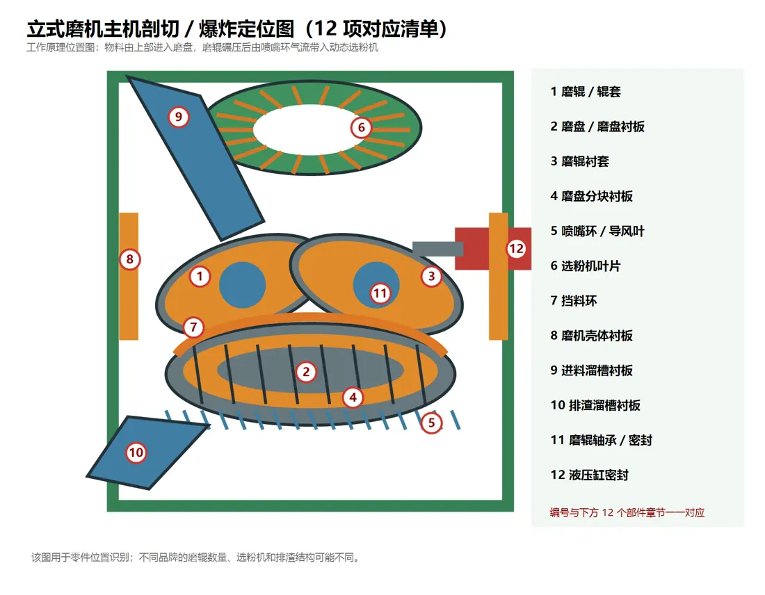
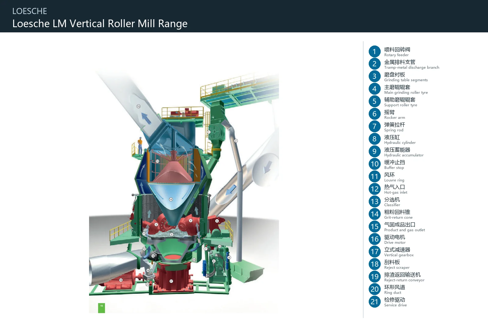
Component Location Diagram

The numbers on the diagram correspond one to one with the rows below.

LOESCHE vertical roller mill – Component Location Diagram
Pictured model: LM cement/slag mill with M and S rollers
No.ComponentLocationApplies to
1Rotary feederAssembly or working region identified by OEM figure item 1LM cement/slag mill with M and S rollers
2Tramp-metal discharge branchAssembly or working region identified by OEM figure item 2LM cement/slag mill with M and S rollers
3Grinding table segmentsAssembly or working region identified by OEM figure item 3LM cement/slag mill with M and S rollers
4Main grinding roller tyreAssembly or working region identified by OEM figure item 4LM cement/slag mill with M and S rollers
5Support roller tyreAssembly or working region identified by OEM figure item 5LM cement/slag mill with M and S rollers
6Rocker armAssembly or working region identified by OEM figure item 6LM cement/slag mill with M and S rollers
7Spring rodAssembly or working region identified by OEM figure item 7LM cement/slag mill with M and S rollers
8Hydraulic cylinderAssembly or working region identified by OEM figure item 8LM cement/slag mill with M and S rollers
9Hydraulic accumulatorAssembly or working region identified by OEM figure item 9LM cement/slag mill with M and S rollers
10Buffer stopAssembly or working region identified by OEM figure item 10LM cement/slag mill with M and S rollers
11Louvre ringAssembly or working region identified by OEM figure item 11LM cement/slag mill with M and S rollers
12Hot-gas inletAssembly or working region identified by OEM figure item 12LM cement/slag mill with M and S rollers
13ClassifierAssembly or working region identified by OEM figure item 13LM cement/slag mill with M and S rollers
14Grit-return coneAssembly or working region identified by OEM figure item 14LM cement/slag mill with M and S rollers
15Product and gas outletAssembly or working region identified by OEM figure item 15LM cement/slag mill with M and S rollers
16Drive motorAssembly or working region identified by OEM figure item 16LM cement/slag mill with M and S rollers
17Vertical gearboxAssembly or working region identified by OEM figure item 17LM cement/slag mill with M and S rollers
18Reject scraperAssembly or working region identified by OEM figure item 18LM cement/slag mill with M and S rollers
19Reject-return conveyorAssembly or working region identified by OEM figure item 19LM cement/slag mill with M and S rollers
20Ring ductAssembly or working region identified by OEM figure item 20LM cement/slag mill with M and S rollers
21Service driveAssembly or working region identified by OEM figure item 21LM cement/slag mill with M and S rollers
Wear Parts

Identify Wear Parts by Installation Position

These general Vertical Mill part categories help identify the part you need. Confirm suitability against the specific LOESCHE model and drawings.

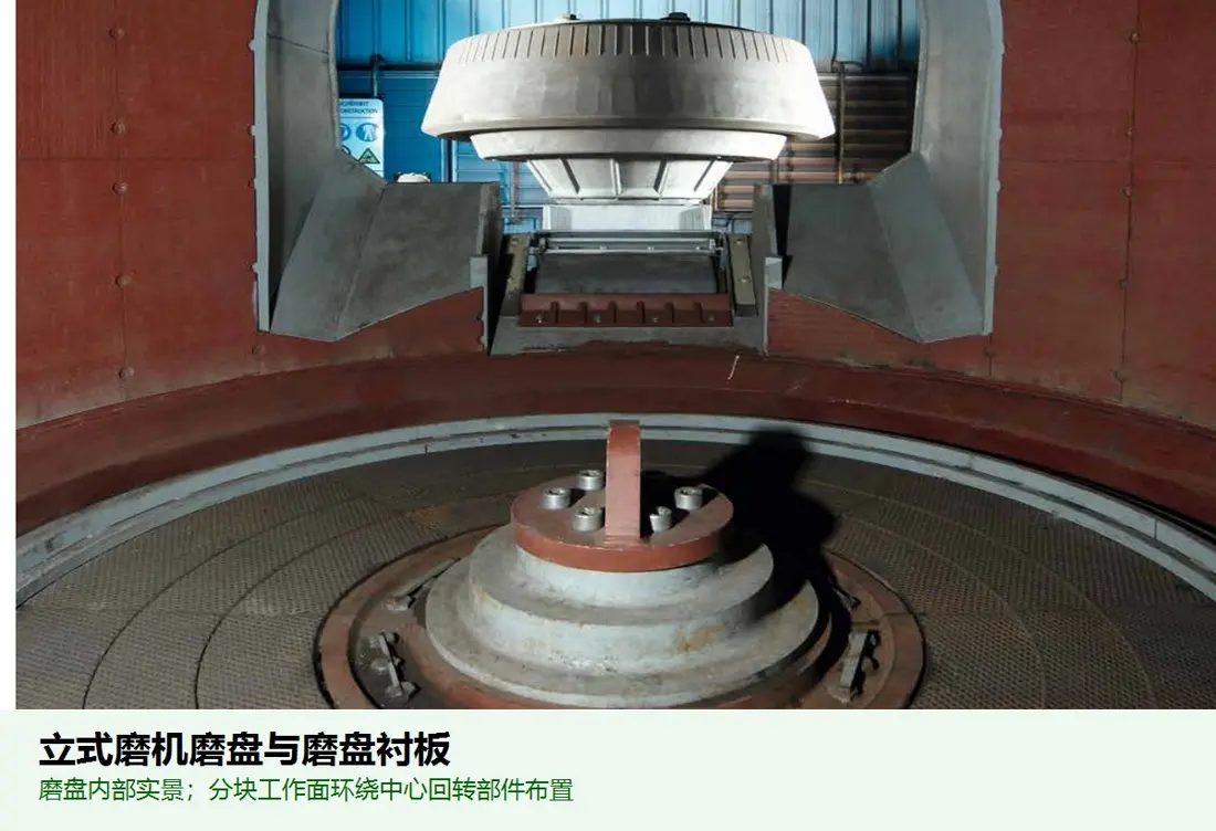
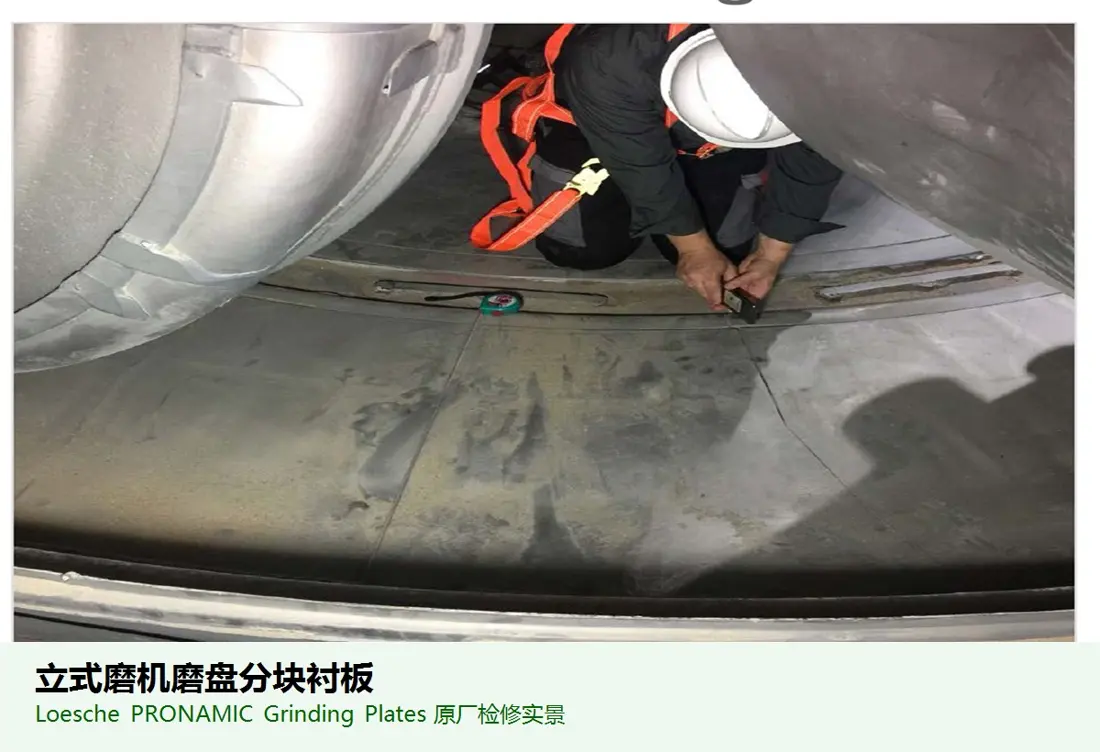
Illustration of the general grinding table / table liner assembly category
01

Grinding Table / Table Liner Assembly

Grinding Table / Table Liner

A general wear part category for Vertical Mill equipment. Confirm the installation position, profile, hole pattern, material and machine model against the equipment drawing. The image illustrates a part category and is not an OEM drawing.

View General Part Details →
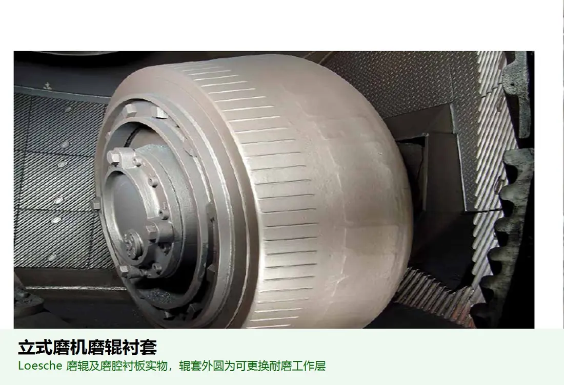
Illustration of the general grinding roller sleeve category
02

Grinding Roller Sleeve

Roller Liner / Roller Sleeve

A general wear part category for Vertical Mill equipment. Confirm the installation position, profile, hole pattern, material and machine model against the equipment drawing. The image illustrates a part category and is not an OEM drawing.

View General Part Details →
Illustration of the general segmented grinding table liner category
03

Segmented Grinding Table Liner

Table Segments / Grinding Plates

A general wear part category for Vertical Mill equipment. Confirm the installation position, profile, hole pattern, material and machine model against the equipment drawing. The image illustrates a part category and is not an OEM drawing.

View General Part Details →
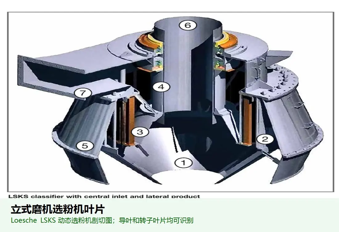
Illustration of the general air classifier blade category
04

Air Classifier Blade

Classifier Blade / Vane

A general wear part category for Vertical Mill equipment. Confirm the installation position, profile, hole pattern, material and machine model against the equipment drawing. The image illustrates a part category and is not an OEM drawing.

View General Part Details →
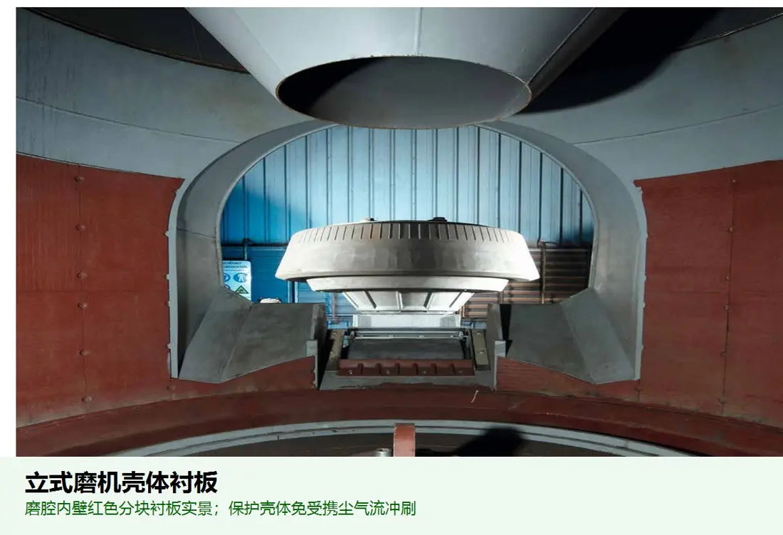
Illustration of the general mill shell liner category
05

Mill Shell Liner

Mill Body Liner / Housing Liner

A general wear part category for Vertical Mill equipment. Confirm the installation position, profile, hole pattern, material and machine model against the equipment drawing. The image illustrates a part category and is not an OEM drawing.

View General Part Details →
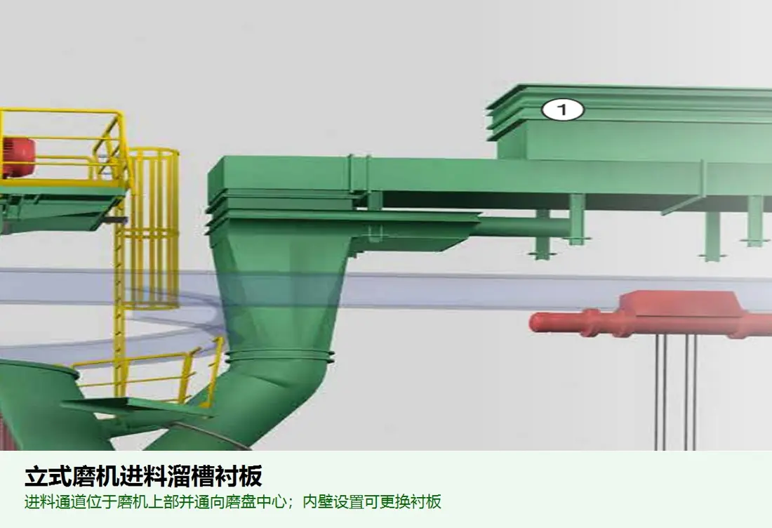
Illustration of the general feed chute liner category
06

Feed Chute Liner

Feed Chute Liner

A general wear part category for Vertical Mill equipment. Confirm the installation position, profile, hole pattern, material and machine model against the equipment drawing. The image illustrates a part category and is not an OEM drawing.

View General Part Details →
Spare Parts

Drive, Load-Bearing and Structural Parts

Identify gears, shafts, sleeves, bearings, seals, hydraulic parts, supports and connectors for drawing review. Listed OEM drawing or part references relate to identified parts and require confirmation against your machine.

Illustration of the general grinding roller sleeve category
01

Grinding Roller Sleeve

Roller Liner / Roller Sleeve

A general structural or drive part category for Vertical Mill equipment. Confirm interfaces, accuracy, material and machine model against the equipment drawing. The image illustrates a part category and is not an OEM drawing.

View General Part Details →
Illustration of the general grinding roller bearing / seal category
02

Grinding Roller Bearing / Seal

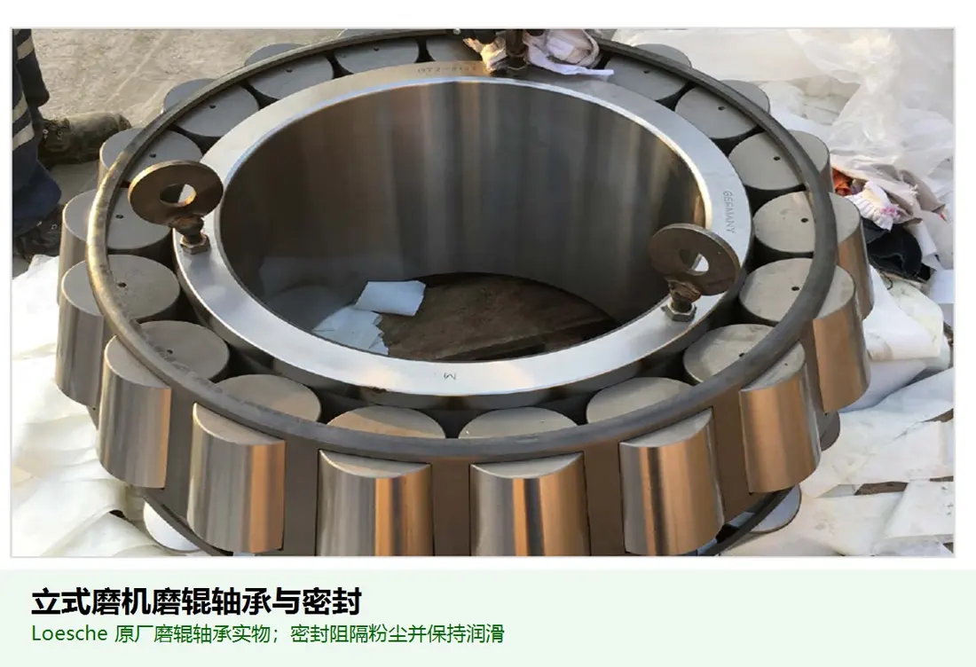
Roller Bearing / Bearing Seal

A general structural or drive part category for Vertical Mill equipment. Confirm interfaces, accuracy, material and machine model against the equipment drawing. The image illustrates a part category and is not an OEM drawing.

View General Part Details →
Illustration of the general hydraulic cylinder seal category
03

Hydraulic Cylinder Seal

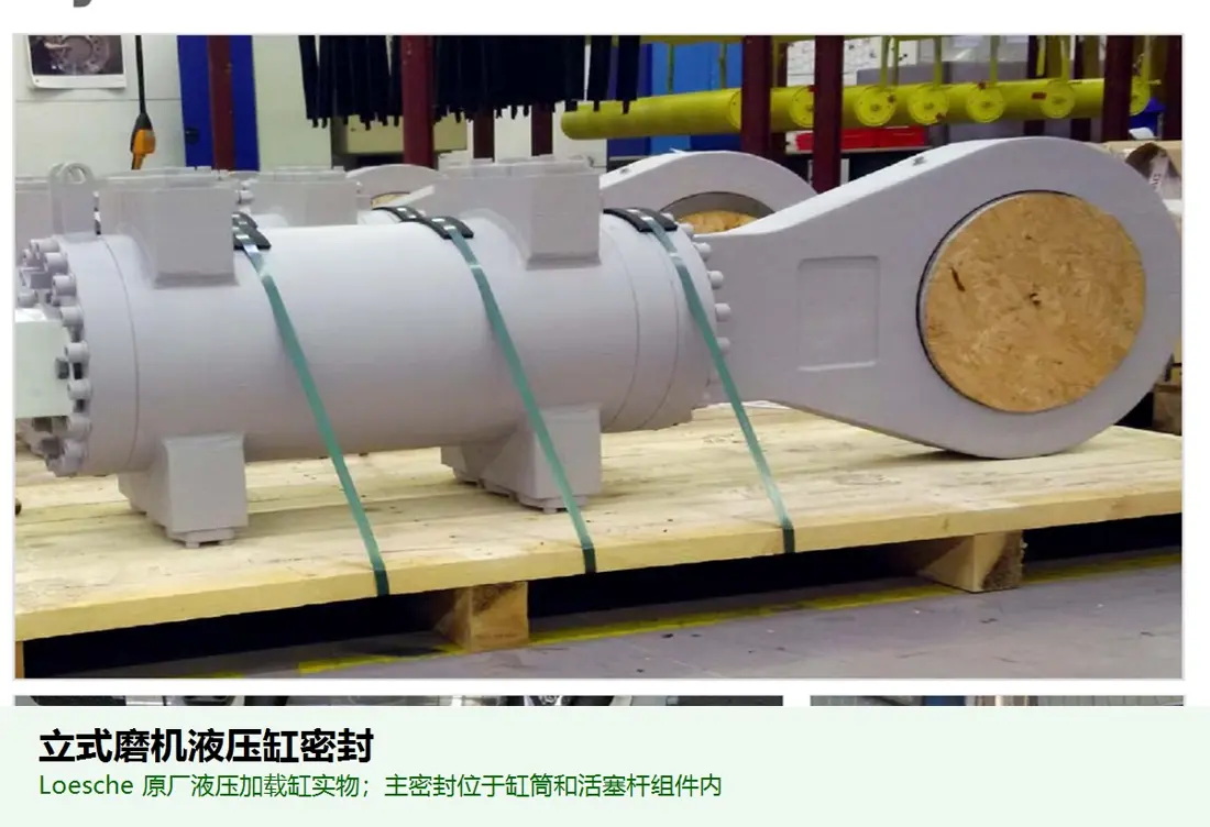
Hydraulic Cylinder Seal

A general structural or drive part category for Vertical Mill equipment. Confirm interfaces, accuracy, material and machine model against the equipment drawing. The image illustrates a part category and is not an OEM drawing.

View General Part Details →
FAQ

Frequently asked questions

What information is needed to quote parts for LOESCHE vertical roller mill?

Provide the complete model, serial number, drawing revision, installation position, photographs of the current part, material and operating conditions.

Can a general part image be used directly for manufacture?

No. General images help identify the part category. Manufacture requires agreed drawings, dimensions, interfaces, materials and acceptance criteria.

Can a part be assessed without an drawing?

Start with the nameplate, general arrangement drawing, installation position, used-part photographs and key dimensions. We can then assess the feasibility of dimensional inspection, material evaluation and manufacture to drawing.

Send Your LOESCHE vertical roller mill Model or Drawing

Provide the complete model, serial number, nameplate, installation position, photographs of the current part, drawings, material and operating conditions. We use these to identify the part, assess materials, organize production at certified foundries, coordinate quality control and arrange finished-part delivery.

Equipment Brand and ModelDrawingDrawing or DimensionsCurrent MaterialPhotographs of Failed PartsTarget Service LifeOperating Conditions
Request a Quote

Or contact us directly: +86 156 3797 3199
zzx@anranst.com

Manufacturing Services in China

From Technical Assessment to Finished-Part Delivery

ANRANST provides customers worldwide with engineering assessment, production at certified foundries to the customer technical requirements, quality control and finished-part delivery for custom wear parts and industrial spares, with scope to support other custom industrial parts.

01

Drawing and Engineering Review

We review mating surfaces and interface dimensions and assess material, heat treatment and manufacturing feasibility.

02

Material and Heat-Treatment Specification

Material grades and heat-treatment processes are specified order by order, stated in the technical agreement and tracked through production.

03

Quality Control

Drawing confirmation, material and process control, production tracking, inspection and acceptance coordination.

04

Finished-Part Delivery

We coordinate manufacturing, quality confirmation, packaging and delivery of complete finished parts in a workable, closed-loop supply process.

Provide the existing model, drawings, drawing, materials or operating conditions so we can identify the appropriate technical review and supply route.

Submit an Enquiry