
Which models does the LM CS cover?
The LM CS covers 9 models: LM D, LM 2+2, LM 3+3, LM 4+4, LM, LM, LM 3.6, LM, LM M. Former and renamed designations are listed in the models table on this page.
2026-10 · 9 models
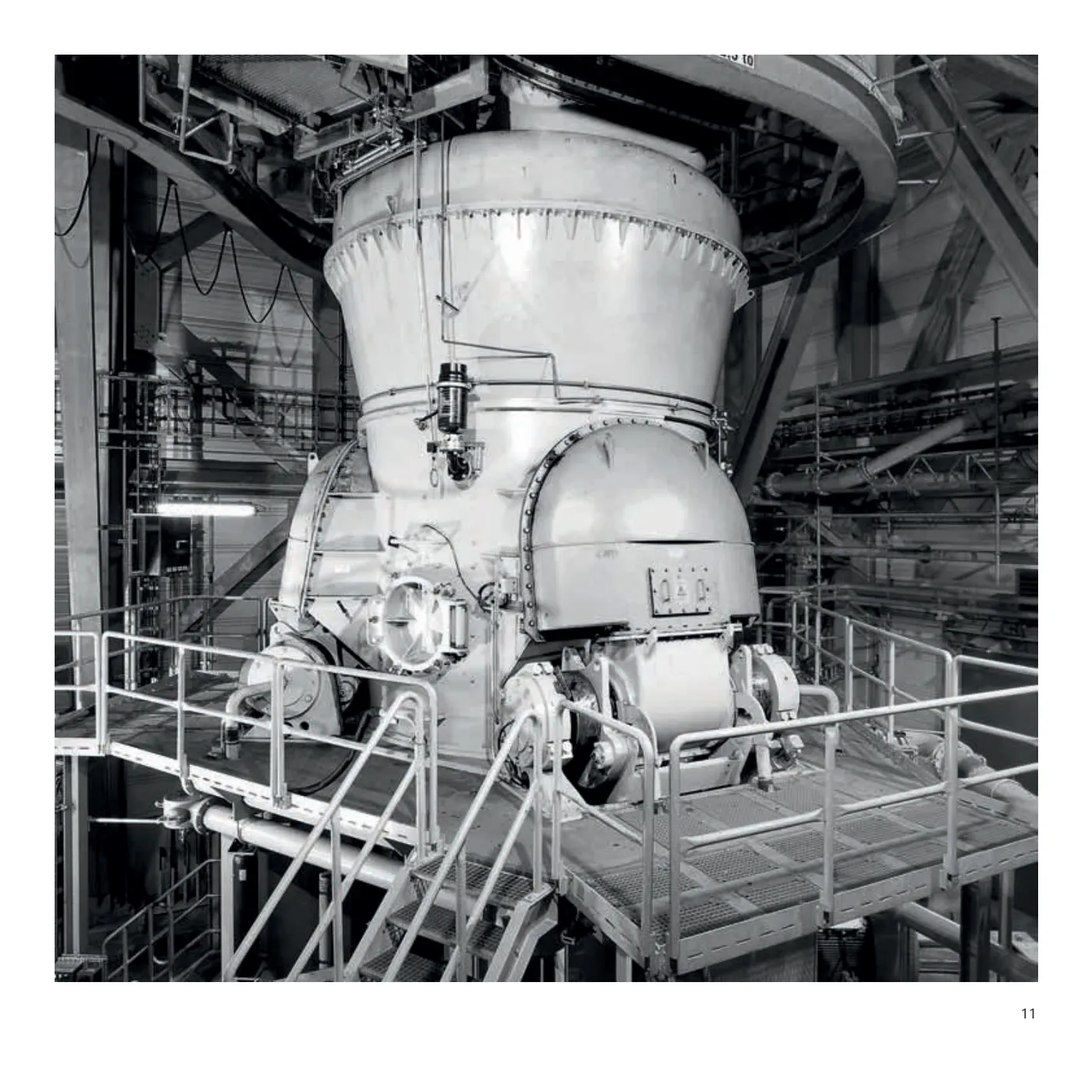
Select a model to jump to its component table; former and renamed designations are listed under “Historical names / renamings”.
| Model | Historical names / renamings | Period | Components |
|---|---|---|---|
| LM D | LM 12.2 D; LM 26.3 D; LM 21.2 D; LM 23.2 D; LM 43.4 D; LM 28.2 D; LM 20.2 D; LM 19.2 D; LM 17.2 D; LM 16.2 D; LM 15.2 D; LM 14.2 D; LM 13.2 D; LM 53.6 D; LM 41.4 D; LM 35.3 D; LM 28.3 D; LM 27.2 D | 2026-10 | 6 |
| LM 2+2 | LM 35.2+2; LM 46.2+2; LM 56.2+2; LM 35.2+2 CS; LM 41.2+2 CS; LM 46.2+2 CS; LM 48.2+2 CS; LM 56.2+2 CS | 1990 —2016 | 6 |
| LM 3+3 | LM 56.3+3; LM 53.3+3 CS; LM 56.3+3 CS; LM 59.3+3 CS; LM 63.3+3 CS | 1990 —2016 | 6 |
| LM 4+4 | LM 65.4+4 CS; LM 70.4+4 CS; LM 75.4+4 CS; LM 72.4+4 CS | 1990 —2016 | 6 |
| LM | LM 15.2 CS; LM 24.2 CS | 2026-10 | 6 |
| LM | LM 12.200; LM 15.200 | 2026-10 | 6 |
| LM 3.6 | 2026-10 | 2 | |
| LM | LM 16; LM 20; LM 22; LM 28; LM 46.4; LM 30.4; LM 32.4; LM 36.4; LM 43.4; LM 50.4; LM 63.4; LM 60.6; LM 69.4; LM 69.6; LM 45.4; LM 60.4; LM 75.6; LM 70.5; LM 56.6; LM 56.4; LM 53.6; LM 48.4; LM 41.4; LM 38.4; LM 35.4; LM 38.3; LM 31.3; LM 31.2; LM 24.2; LM 21.2; LM 19.2; LM 15.2; LM 12.2; LM 18 | 1928—2016 | 6 |
| LM M | LM 12.2M; LM 15.2M; LM 17.2M; LM 19.2M; LM 21.2M; LM 24.2M; LM 15.200 | 2026-10 | 7 |
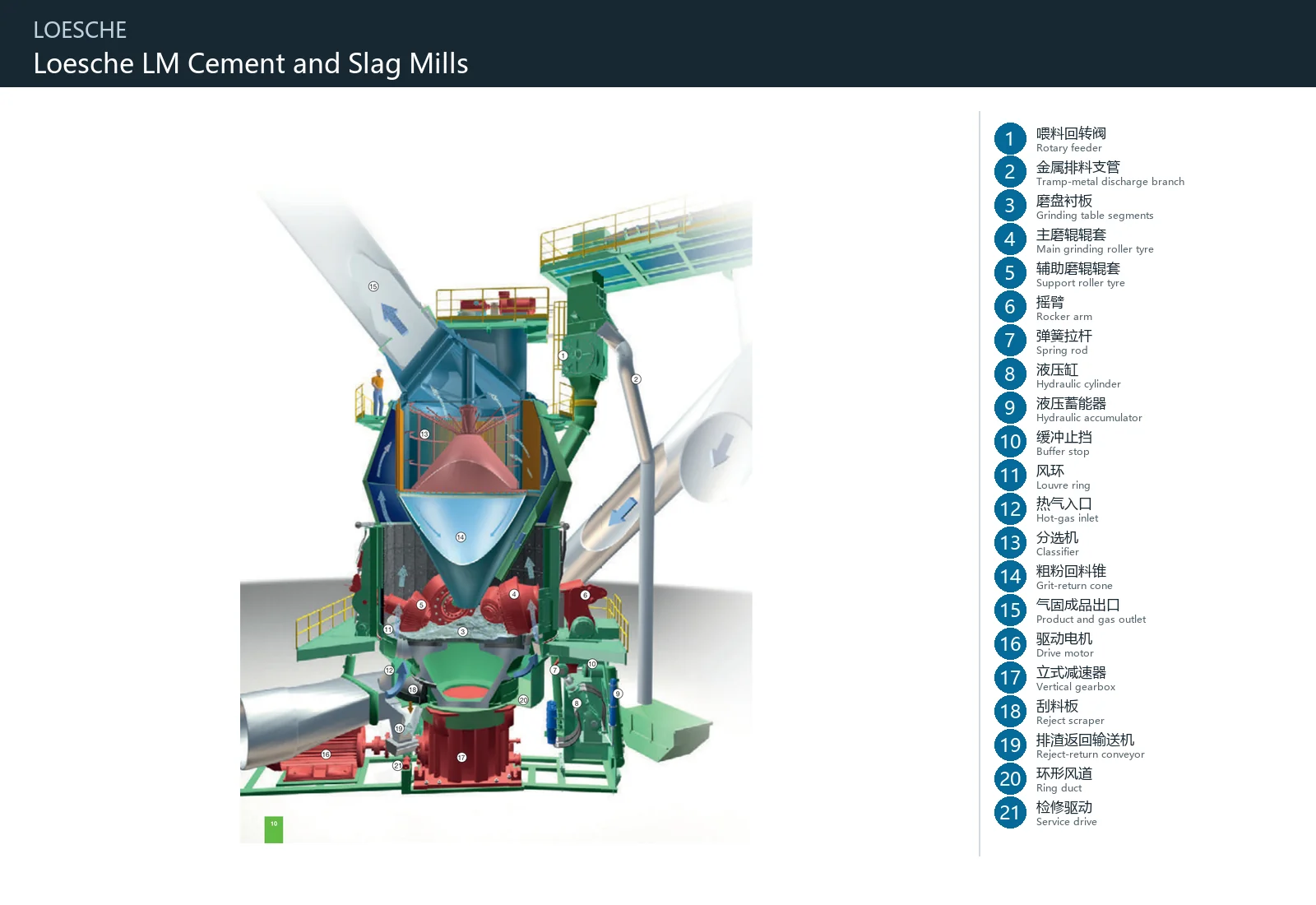
The numbers on the diagram correspond one to one with the rows below.
| No. | Component | Location | Applies to |
|---|---|---|---|
| 1 | Rotary feeder | Assembly or working region identified by OEM figure item 1 | LM cement/slag mill with M and S rollers |
| 2 | Tramp-metal discharge branch | Assembly or working region identified by OEM figure item 2 | LM cement/slag mill with M and S rollers |
| 3 | Grinding table segments | Assembly or working region identified by OEM figure item 3 | LM cement/slag mill with M and S rollers |
| 4 | Main grinding roller tyre | Assembly or working region identified by OEM figure item 4 | LM cement/slag mill with M and S rollers |
| 5 | Support roller tyre | Assembly or working region identified by OEM figure item 5 | LM cement/slag mill with M and S rollers |
| 6 | Rocker arm | Assembly or working region identified by OEM figure item 6 | LM cement/slag mill with M and S rollers |
| 7 | Spring rod | Assembly or working region identified by OEM figure item 7 | LM cement/slag mill with M and S rollers |
| 8 | Hydraulic cylinder | Assembly or working region identified by OEM figure item 8 | LM cement/slag mill with M and S rollers |
| 9 | Hydraulic accumulator | Assembly or working region identified by OEM figure item 9 | LM cement/slag mill with M and S rollers |
| 10 | Buffer stop | Assembly or working region identified by OEM figure item 10 | LM cement/slag mill with M and S rollers |
| 11 | Louvre ring | Assembly or working region identified by OEM figure item 11 | LM cement/slag mill with M and S rollers |
| 12 | Hot-gas inlet | Assembly or working region identified by OEM figure item 12 | LM cement/slag mill with M and S rollers |
| 13 | Classifier | Assembly or working region identified by OEM figure item 13 | LM cement/slag mill with M and S rollers |
| 14 | Grit-return cone | Assembly or working region identified by OEM figure item 14 | LM cement/slag mill with M and S rollers |
| 15 | Product and gas outlet | Assembly or working region identified by OEM figure item 15 | LM cement/slag mill with M and S rollers |
| 16 | Drive motor | Assembly or working region identified by OEM figure item 16 | LM cement/slag mill with M and S rollers |
| 17 | Vertical gearbox | Assembly or working region identified by OEM figure item 17 | LM cement/slag mill with M and S rollers |
| 18 | Reject scraper | Assembly or working region identified by OEM figure item 18 | LM cement/slag mill with M and S rollers |
| 19 | Reject-return conveyor | Assembly or working region identified by OEM figure item 19 | LM cement/slag mill with M and S rollers |
| 20 | Ring duct | Assembly or working region identified by OEM figure item 20 | LM cement/slag mill with M and S rollers |
| 21 | Service drive | Assembly or working region identified by OEM figure item 21 | LM cement/slag mill with M and S rollers |
| Component |
|---|
| Dam ring |
| Grinding roller tyre |
| Metal discharge system |
| Laboratory grinding roller |
| Laboratory grinding table |
Models with the same components are grouped together; select a group to open its component table.
Models: LM D, LM, LM, LM
| No. | Component | Location |
|---|---|---|
| 1 | Feed rotary valve | Mill feed inlet |
| 3 | Table Segments / Grinding Plates | Working track of the rotating grinding table |
| 6 | Ranging arm | Connection between the grinding roller and the mill frame |
| 8 | Hydraulic cylinder | Grinding roller loading and lifting mechanism |
| Roller Liner / Roller Sleeve | Working face on the outer circumference of the grinding roller in contact with material | |
| Dam Ring / Retention Ring | Outer edge of the grinding table |
Models: LM 2+2, LM 3+3, LM 4+4
| No. | Component | Location |
|---|---|---|
| 3 | Table Segments / Grinding Plates | Working track of the rotating grinding table |
| 4 | Roller Liner / Roller Sleeve | |
| 5 | Roller Liner / Roller Sleeve | |
| 6 | Ranging arm | Connection between the grinding roller and the mill frame |
| 9 | Hydraulic Accumulator | Grinding roller loading hydraulic circuit |
| Dam Ring / Retention Ring | Outer edge of the grinding table |
| No. | Component | Location |
|---|---|---|
| 1 | Feed rotary valve | Mill feed inlet |
| 3 | Table Segments / Grinding Plates | Working track of the rotating grinding table |
| 6 | Ranging arm | Connection between the grinding roller and the mill frame |
| 8 | Hydraulic cylinder | Grinding roller loading and lifting mechanism |
| Roller Liner / Roller Sleeve | Working face on the outer circumference of the grinding roller in contact with material | |
| Dam Ring / Retention Ring | Outer edge of the grinding table | |
| Metal discharge mechanism | Metal recovery outlet at the lower part of the mill |
| Component | Location |
|---|---|
| Test grinding roller | Grinding chamber of the laboratory mill |
| Test grinding table | Bottom of the grinding chamber of the laboratory mill |
The LM CS covers 9 models: LM D, LM 2+2, LM 3+3, LM 4+4, LM, LM, LM 3.6, LM, LM M. Former and renamed designations are listed in the models table on this page.
The LM CS is also documented under these designations: LM D, LM 12.2 D, LM 26.3 D, LM 21.2 D, LM 23.2 D, LM 43.4 D, LM 28.2 D, LM 20.2 D, LM 19.2 D, LM 17.2 D, LM 16.2 D, LM 15.2 D, LM 14.2 D, LM 13.2 D.
The LM CS is listed under the LOESCHE brand. Period: 2026-10. Status: Historical model.
12 components are recorded, including: Roller Liner / Roller Sleeve, Table Segments / Grinding Plates, Dam Ring / Retention Ring, Roller Liner / Roller Sleeve, Roller Liner / Roller Sleeve, Ranging arm, Hydraulic cylinder, Feed rotary valve and more. The full list with locations is in the components table on this page.
Model-specific components with their own page: Ranging arm, Hydraulic cylinder, Feed rotary valve, Hydraulic Accumulator, Test grinding roller, Test grinding table, Metal discharge mechanism (7 in total).
Send us a drawing or sample and tell us the equipment model and part name.
Provide the equipment model, drawing for engineering review and quotation. If service life or wear is a concern, describe the operating conditions as well.
Or contact us directly: +86 156 3797 3199
zzx@anranst.com
ANRANST provides customers worldwide with engineering assessment, production at certified foundries to the customer technical requirements, quality control and finished-part delivery for custom wear parts and industrial spares, with scope to support other custom industrial parts.
We review mating surfaces and interface dimensions and assess material, heat treatment and manufacturing feasibility.
Material grades and heat-treatment processes are specified order by order, stated in the technical agreement and tracked through production.
Drawing confirmation, material and process control, production tracking, inspection and acceptance coordination.
We coordinate manufacturing, quality confirmation, packaging and delivery of complete finished parts in a workable, closed-loop supply process.
Provide the equipment brand, complete model and serial number, part name, part number or drawing number, drawing revision, quantity, material requirements and duty. If identifiers are unavailable, send photographs and key dimensions.
Submit an Enquiry