
KREBS gMAX hydrocyclone

Start with the brand, equipment series and installed machine, then explore wear parts, drive and structural spares, materials and processes, drawing review, quality control and finished-part delivery.

Hydrocyclone equipment or structural illustration 1
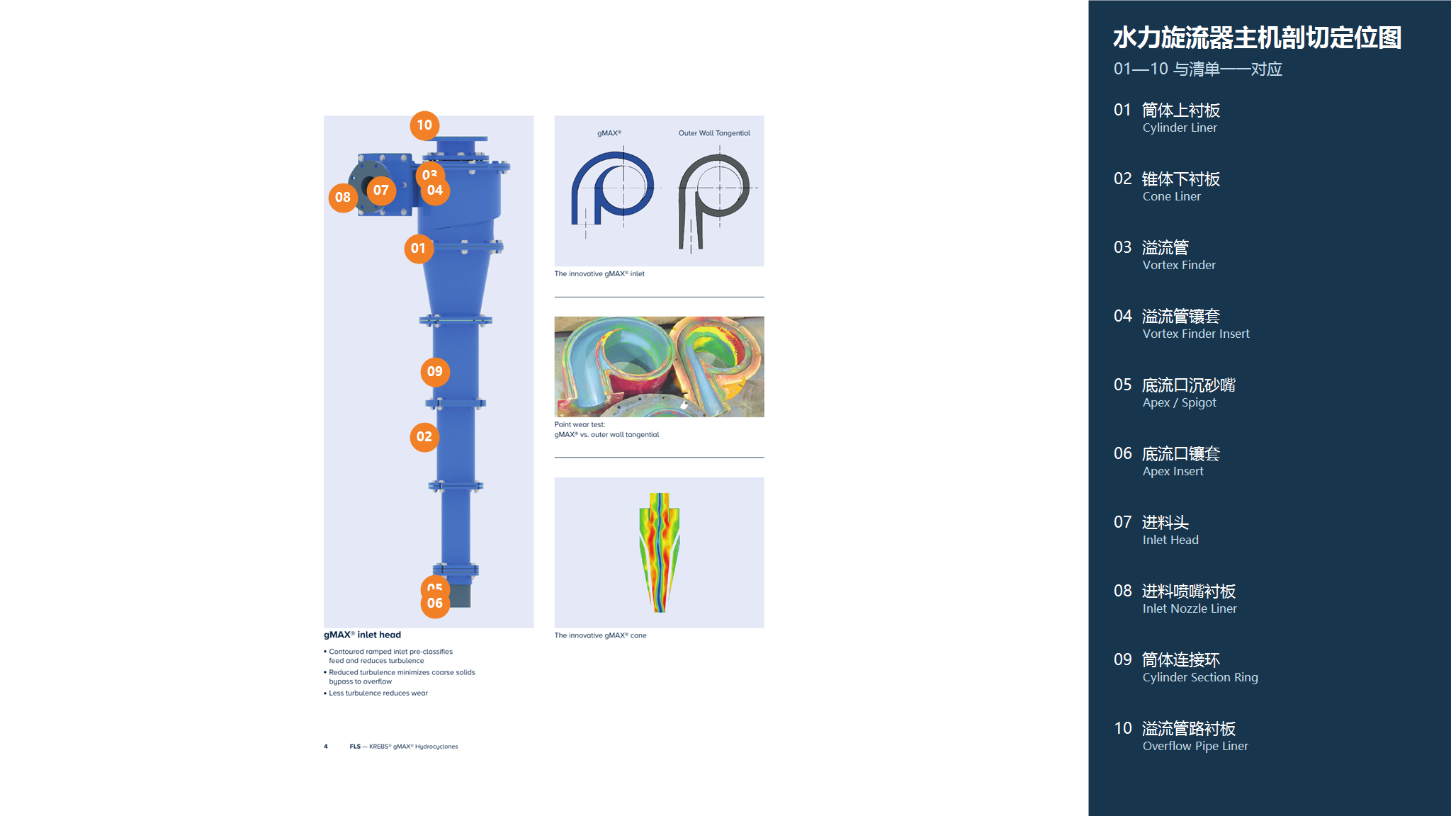
Hydrocyclone illustration showing the equipment layout and main system positions. Identify the exact model and configuration from the nameplate, general arrangement and OEM documentation.
Hydrocyclone equipment or structural illustration 2
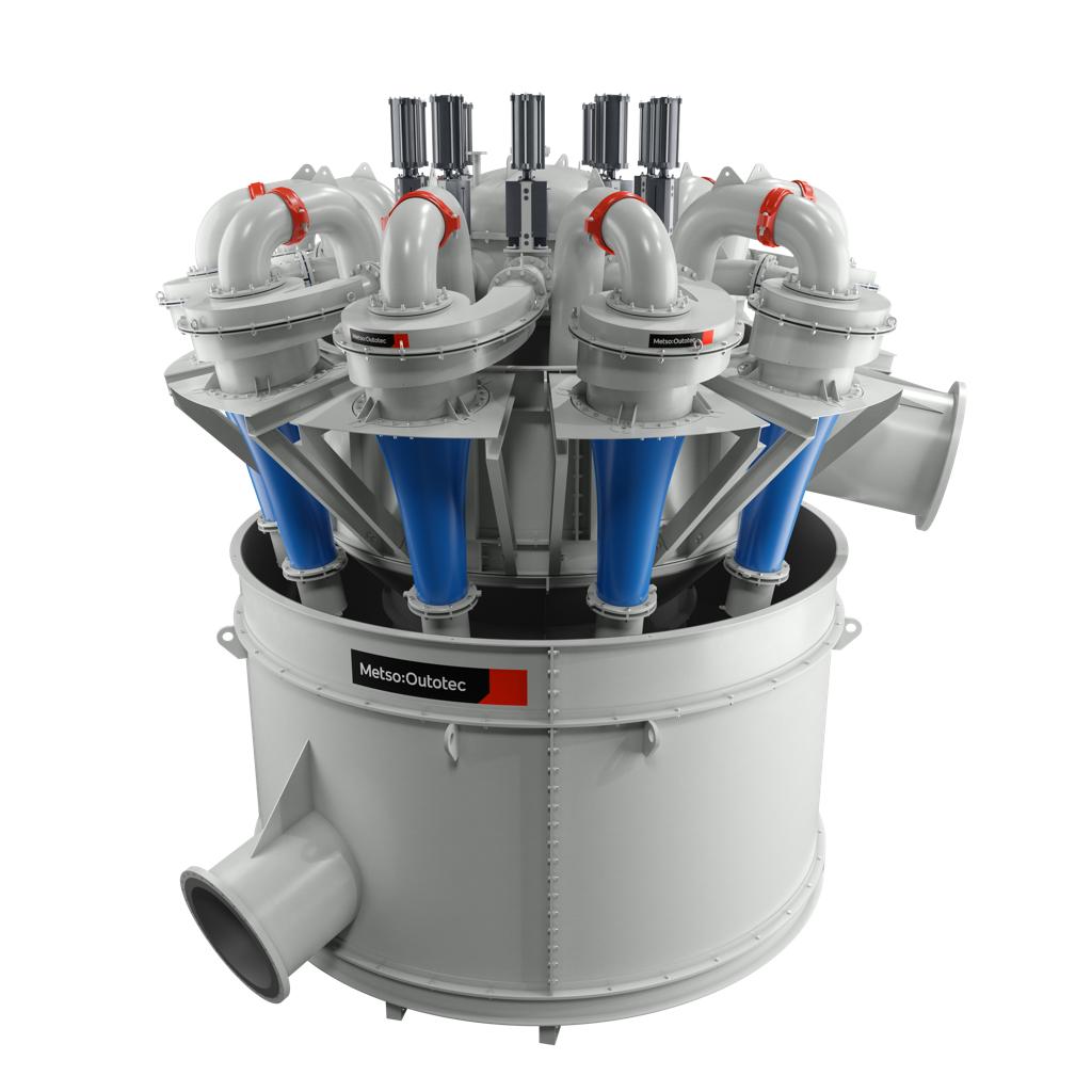
Hydrocyclone illustration showing the equipment layout and main system positions. Identify the exact model and configuration from the nameplate, general arrangement and OEM documentation.
OEM Equipment Series

Identify the Machine, Then Select Parts and Materials

This page covers equipment series and models, part locations, materials and processes, drawing review and inquiry options. Before manufacture or quotation, confirm OEM drawing numbers, dimensions and tooling suitability against the complete model and drawings.

Hydrocyclone General Equipment Categories
1 Equipment Identification Entries
4 Related Wear Parts
6 Related Spare Parts
Models and Identification

gMAX hydrocyclone Series and Installed Equipment

The model table assists with machine identification. Manufacture and quotation require the nameplate, complete model, serial number, drawing number, general arrangement and drawing revision.

Series / ModelEquipment Range and IdentificationEquipment History and Identification
U0.50.5" (13 mm) urethane hydrocyclone; capacity 0.7–1.2 GPM (0.2–0.3 m³/h)KREBS urethane hydrocyclone capacity table; inlet pressure 10–30 psi
gMAX1U1" (25 mm) urethane hydrocyclone; capacity 2.9–4.9 GPM (0.7–1.1 m³/h)KREBS urethane hydrocyclone capacity table; inlet pressure 10–30 psi
U2-gMAX2" (51 mm) urethane hydrocyclone; capacity 7.4–24 GPM (1.7–5.5 m³/h)KREBS urethane hydrocyclone capacity table; inlet pressure 10–30 psi
U3-gMAX3" (76 mm) urethane hydrocyclone; capacity 14–55 GPM (3.2–12.5 m³/h)KREBS urethane hydrocyclone capacity table; inlet pressure 10–30 psi
gMAX4U4" (102 mm) urethane hydrocyclone; capacity 24–76 GPM (5.4–17.3 m³/h)KREBS urethane hydrocyclone capacity table; inlet pressure 10–30 psi
gMAX6U6" (152 mm) urethane hydrocyclone; capacity 57–147 GPM (13–33 m³/h)KREBS urethane hydrocyclone capacity table; inlet pressure 10–30 psi
gMAX10U10" (254 mm) urethane hydrocyclone; capacity 96–500 GPM (22–114 m³/h)KREBS urethane hydrocyclone capacity table; inlet pressure 10–30 psi
gMAX15U15" (381 mm) urethane hydrocyclone; capacity 500–1,200 GPM (114–273 m³/h)KREBS urethane hydrocyclone capacity table; inlet pressure 10–30 psi
gMAX steel hydrocyclonesSteel housings, 1"–30" (25–762 mm) in diameter, with bonded or replaceable rubber linings for mineral processing, water treatment and chemical separationKREBS steel-housed hydrocyclone range
Wear Parts

Identify Wear Parts by Installation Position

These general Hydrocyclone part categories help identify the part you need. Confirm suitability against the specific KREBS model and drawings.

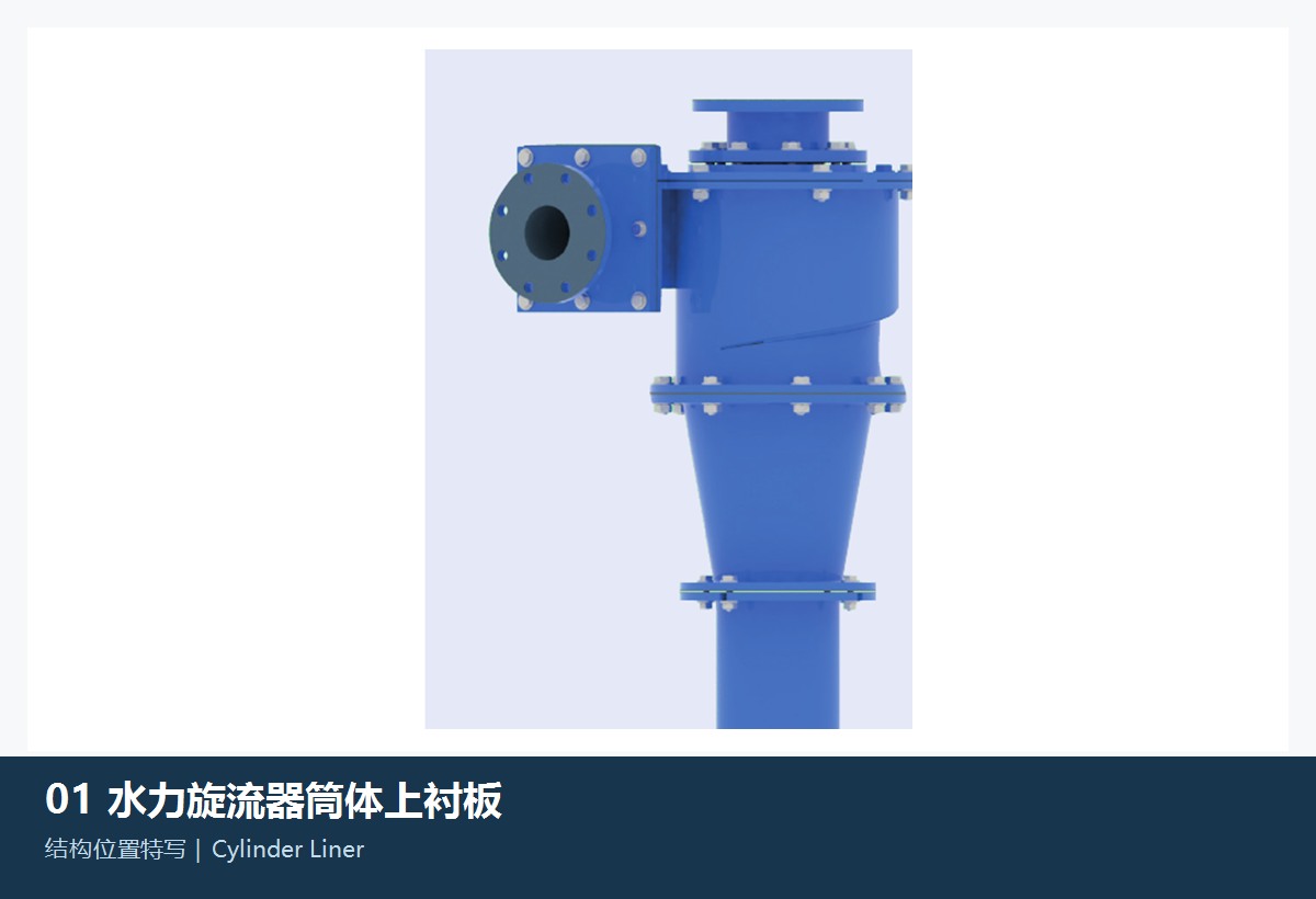
Illustration of the general cylindrical section liner / upper liner category
01

Cylindrical Section Liner / Upper Liner

Cylinder Liner / Upper Liner

A general wear part category for Hydrocyclone equipment. Confirm the installation position, profile, hole pattern, material and machine model against the equipment drawing. The image illustrates a part category and is not an OEM drawing.

View General Part Details →
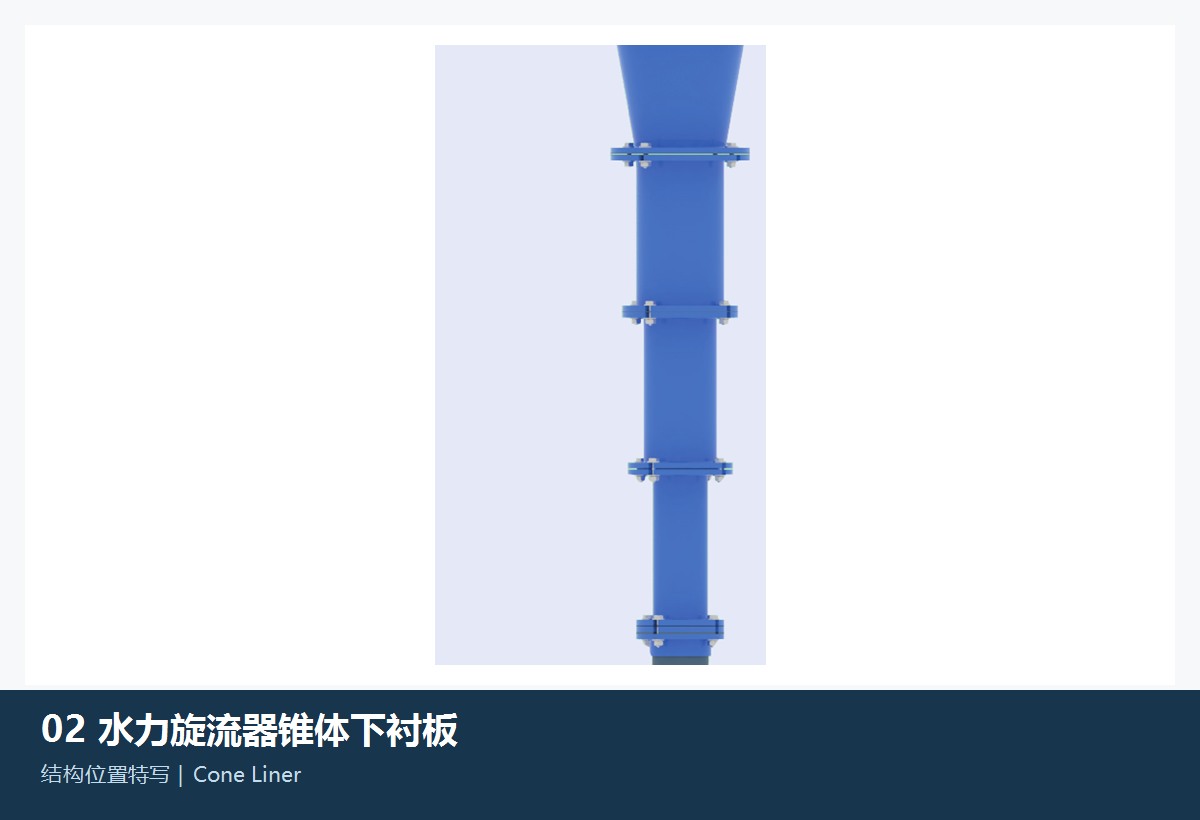
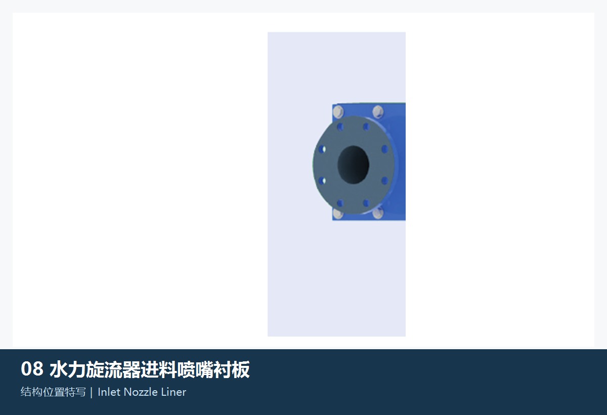
Illustration of the general cone liner / lower liner category
02

Cone Liner / Lower Liner

Cone Liner / Lower Liner

A general wear part category for Hydrocyclone equipment. Confirm the installation position, profile, hole pattern, material and machine model against the equipment drawing. The image illustrates a part category and is not an OEM drawing.

View General Part Details →
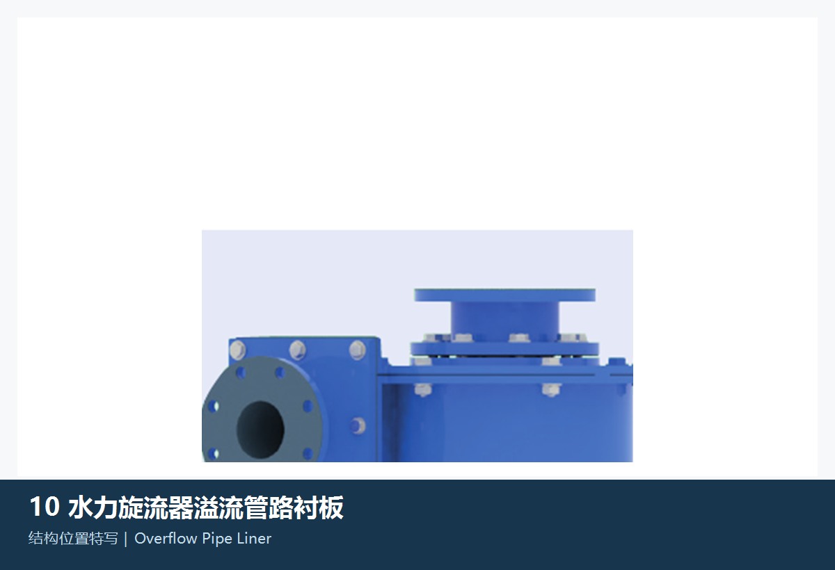
Illustration of the general inlet nozzle liner category
03

Inlet Nozzle Liner

Inlet Nozzle Liner

A general wear part category for Hydrocyclone equipment. Confirm the installation position, profile, hole pattern, material and machine model against the equipment drawing. The image illustrates a part category and is not an OEM drawing.

View General Part Details →
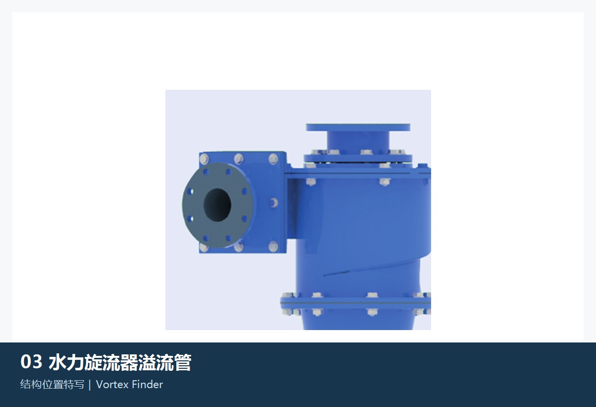
Illustration of the general overflow pipe liner category
04

Overflow Pipe Liner

Overflow Pipe Liner

A general wear part category for Hydrocyclone equipment. Confirm the installation position, profile, hole pattern, material and machine model against the equipment drawing. The image illustrates a part category and is not an OEM drawing.

View General Part Details →
Spare Parts

Drive, Load-Bearing and Structural Parts

Identify gears, shafts, sleeves, bearings, seals, hydraulic parts, supports and connectors for drawing review. Listed OEM drawing or part references relate to identified parts and require confirmation against your machine.

Illustration of the general vortex finder category
01

Vortex Finder

Vortex Finder

A general structural or drive part category for Hydrocyclone equipment. Confirm interfaces, accuracy, material and machine model against the equipment drawing. The image illustrates a part category and is not an OEM drawing.

View General Part Details →
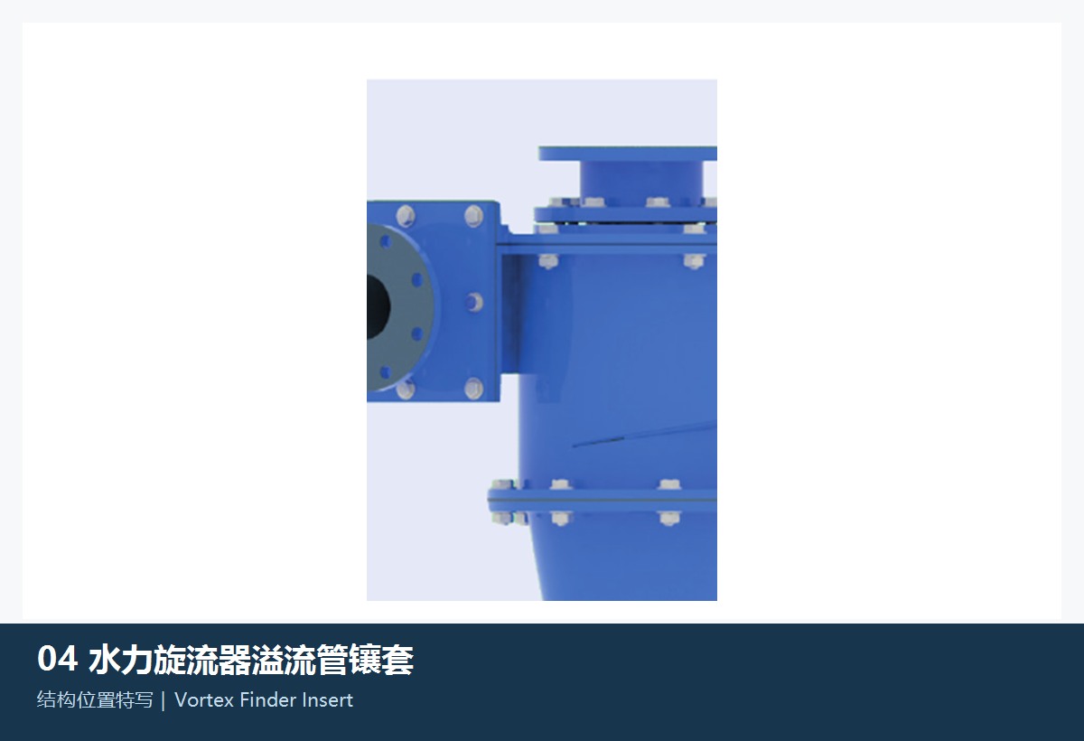
Illustration of the general vortex finder insert category
02

Vortex Finder Insert

Vortex Finder Insert

A general structural or drive part category for Hydrocyclone equipment. Confirm interfaces, accuracy, material and machine model against the equipment drawing. The image illustrates a part category and is not an OEM drawing.

View General Part Details →
Illustration of the general underflow spigot / apex category
03

Underflow Spigot / Apex

Apex / Spigot

A general structural or drive part category for Hydrocyclone equipment. Confirm interfaces, accuracy, material and machine model against the equipment drawing. The image illustrates a part category and is not an OEM drawing.

View General Part Details →
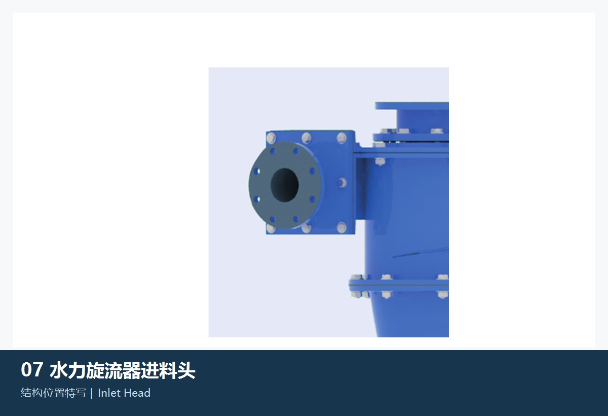
Illustration of the general underflow spigot insert category
04

Underflow Spigot Insert

Apex Insert

A general structural or drive part category for Hydrocyclone equipment. Confirm interfaces, accuracy, material and machine model against the equipment drawing. The image illustrates a part category and is not an OEM drawing.

View General Part Details →
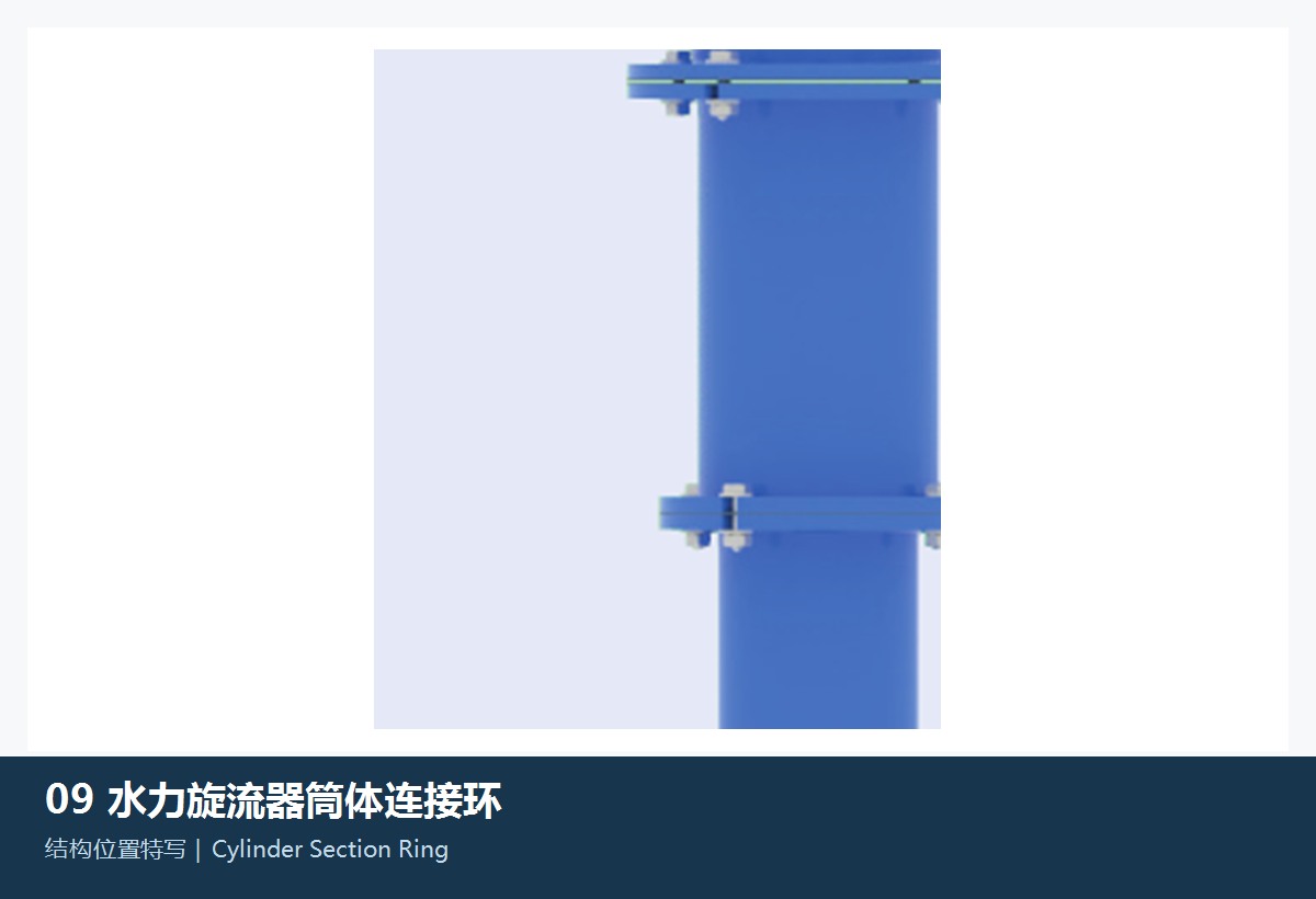
Illustration of the general feed head / feed chamber category
05

Feed Head / Feed Chamber

Inlet Head / Feed Chamber

A general structural or drive part category for Hydrocyclone equipment. Confirm interfaces, accuracy, material and machine model against the equipment drawing. The image illustrates a part category and is not an OEM drawing.

View General Part Details →
Illustration of the general shell connecting ring category
06

Shell Connecting Ring

Cylinder Section Ring

A general structural or drive part category for Hydrocyclone equipment. Confirm interfaces, accuracy, material and machine model against the equipment drawing. The image illustrates a part category and is not an OEM drawing.

View General Part Details →

What information is needed to quote parts for KREBS gMAX Hydrocyclone?

Provide the complete model, serial number, drawing or part number, drawing revision, installation position, photographs of the current part, material and operating conditions.

Can a general part image be used directly for manufacture?

No. General images help identify the part category. Manufacture requires agreed drawings, dimensions, interfaces, materials and acceptance criteria.

Can a part be assessed without an OEM drawing number?

Start with the nameplate, general arrangement drawing, installation position, used-part photographs and key dimensions. We can then assess the feasibility of dimensional inspection, material evaluation and manufacture to drawing.

Send Your KREBS gMAX Hydrocyclone Model or Drawing

Provide the complete model, serial number, nameplate, installation position, photographs of the current part, drawings, material and operating conditions. We use these to identify the part, assess materials, match manufacturing resources, coordinate quality control and arrange finished-part delivery.

Manufacturing Services in China

From Technical Assessment to Finished-Part Delivery

ANRANST provides customers worldwide with coordinated consulting, supplier sourcing, quality control and finished-part delivery for custom parts, wear parts and industrial spares from China, with scope to support other custom industrial parts.

01

Technical Advice

Equipment and part identification, drawing review, material selection and manufacturing feasibility assessment.

02

Supplier Introductions

Match requirements with suitable manufacturers in China and coordinate the exchange of technical information.

03

Quality Control

Drawing confirmation, material and process control, production tracking, inspection and acceptance coordination.

04

Finished-Part Delivery

Coordinate manufacturing, quality confirmation, packaging and delivery of complete finished parts.

Provide the existing model, drawings, drawing or part numbers, materials or operating conditions so we can identify the appropriate technical review and supply route.

Submit an Enquiry