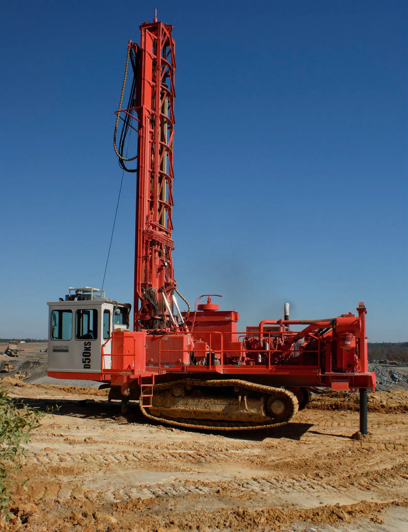
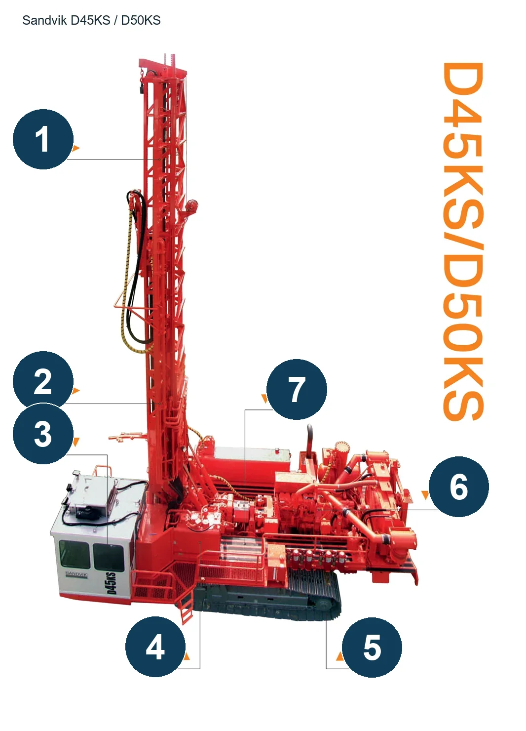
| 1 | Truss type drilling tower | Drilling tool support tower | |
| 2 | Drill pipe handling mechanism | Drilling tower/operating platform | |
| 4 | Hydraulic system | Host power and actuator | 016259-001 / 016328-001 / 019681-001 / 019684-001 |
| 5 | Crawler chassis | Running mechanism of the lower part of the main machine | |
| Propulsion chain | Drilling tower propulsion mechanism | |
| Air compressor | Main engine power set | |
| CMS compressor management system | Air compressor control system | |
| Swing hydraulic motor (1990 D75K) | Two motors, rotary head frame | |
| Sliding swivel head frame (1990 D75K) | Move along the mast | |
| main shaft joint (1990 D75K) | Threaded connection from rotary head to drill pipe | |
| Drill pipe (1990 D75K) | Drill string and rotary table rod changer, three spare rods | |
| Feed chain (1990 D75K) | Make the rotary head move up and down, double cylinder drive | |
| Feed hydraulic cylinder (1990 D75K) | Two pieces, driven chain feed | |
| Rotary Disk Rod Changer (1990 D75K) | Store and replace three spare rods | |
| Independent leveling legs (1990 D75K) | Three leveling supports | |
| Manual console and instrument (1990 D75K) | Rotary speed/feed and rotary pressure/slagging air pressure monitoring | |
| Cooler (D25KS/D245S noun diagram) | Front of machine | |
| Air filter (D25KS/D245S noun diagram) | | |
| Gas storage tank (D25KS/D245S noun diagram) | Compressed air system | |
| Feed chain (D25KS/D245S noun diagram) | Mast feeding mechanism | |
| Turning head (D25KS/D245S noun diagram) | Feed along the mast | |
| Compressor (D25KS/D245S noun diagram) | Power and compressed air system | |
| Mast (D25KS/D245S noun diagram) | Drill pipe/swivel head support | |
| Pump driver (D25KS/D245S noun diagram) | Hydraulic pump transmission | |
| Drill pipe (D25KS/D245S noun diagram) | drill string | |
| Engine (D25KS/D245S noun diagram) | Fuselage power department | |
| Dust collector (D25KS/D245S noun diagram) | Dust collection | |
| Hydraulic oil tank (D25KS/D245S noun diagram) | Hydraulic system | |
| Mast lifting cylinder (D25KS/D245S noun diagram) | Between mast and fuselage | |
| Rod installer (D25KS/D245S noun diagram) | Mast side, specific inner/outer configuration to be found on the original page | |
| Cab (D25KS/D245S noun diagram) | Operator position | |
| Leveling cylinder (D25KS/D245S noun diagram) | Body support | |
| Clamping wrench (D25KS/D245S noun diagram) | Workbench clamping drill pipe | |
| Workbench and dust cover (D25KS/D245S noun diagram) | Above drilling/working area | |
| Track (D25KS/D245S noun diagram) | Walking chassis | |
| main shaft repair sleeve and accompanying installation tools (maintenance information kit) | Worn shaft surface in contact with shaft seal; all package literature numbers are omitted | 009532-001 / 009532-002 |
| Sealed electrical connector kit (maintenance information kit) | Electrical wiring; original Deutsch type two/three-pin connection, number omitted | 019244-112 |
| Pressure gauge/flow meter (maintenance diagnostic tool) | Pump/motor diagnosis; not the normal operating condition of the host. | |
| BECO adapted drill pipe (127/140/152.4/159/165.1 description file) | Drill string; L9144mm, 127/140 uses 3½BECO, and the remaining 4½BECO; 159 corresponds to ØA158.8mm | |
| Mammoth automatic lever wrench (post-installation adapter statement) | Clarify the specified model of the adapter table | |
| D25KS/D245S hydraulic cylinder piston lock upgrade kit | Hydraulic cylinder piston and piston rod thread locking area; only the original locking structure is specified | 020058-055 |