
Drawing and Engineering Review
We review mating surfaces and interface dimensions and assess material, heat treatment and manufacturing feasibility.
Impeller Disc Spacer | Part Specifications and RFQs
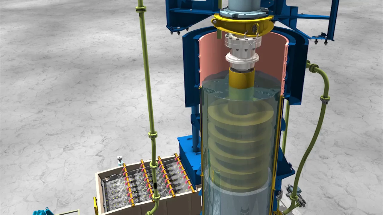
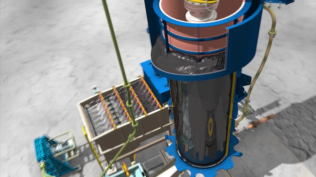
Installed between adjoining impeller discs to establish their axial positions and spacing. Check together with the discs, hubs, vertical shaft, axial fastening and complete layout drawing.
Spacers maintain the designed disc spacing on the vertical shaft, preserving the original chamber energy distribution and transferring axial preload through the disc stack. Spacer length or end-face errors accumulate, affecting disc positions, coaxiality and maintenance assembly.
VXPmill uses removable discs and spacers. Determine spacer material independently of the polyurethane disc material: metal reinforcement, polyurethane coating or other construction must be checked against drawings, original parts and material testing.
| OEM / Series | Application and identification notes |
|---|---|
| Current FLS VXPmill product family | Confirm against disc configuration, spacer position and shaft system drawings |
| FLS VXP2500 | Documented installed model; confirm spacer quantities and lengths against project records |
| FLS VXP10000 | Published project model; the model alone does not determine spacer dimensions |
Send us a drawing or sample and tell us the equipment model and part name. Also provide the full model, serial number, spacer position, disc layout drawing, inside and outside diameters, length, end-face details, shaft interface, assembly sequence, used-part photographs, material tests and wear records.
Send us a drawing or sample and tell us the equipment model and part name. Also provide the full model, serial number, spacer position, disc layout drawing, inside and outside diameters, length, end-face details, shaft interface, assembly sequence, used-part photographs, material tests and wear records.
Or contact us directly: +86 156 3797 3199
zzx@anranst.com
ANRANST provides customers worldwide with engineering assessment, production at certified foundries to the customer technical requirements, quality control and finished-part delivery for custom wear parts and industrial spares, with scope to support other custom industrial parts.
We review mating surfaces and interface dimensions and assess material, heat treatment and manufacturing feasibility.
Material grades and heat-treatment processes are specified order by order, stated in the technical agreement and tracked through production.
Drawing confirmation, material and process control, production tracking, inspection and acceptance coordination.
We coordinate manufacturing, quality confirmation, packaging and delivery of complete finished parts in a workable, closed-loop supply process.
Provide the equipment brand, complete model and serial number, part name, part number or drawing number, drawing revision, quantity, material requirements and duty. If identifiers are unavailable, send photographs and key dimensions.
Submit an Enquiry