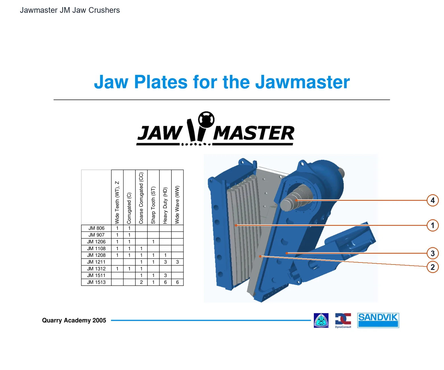
| 1 | Fixed Jaw Plate | Stationary Jaw Plate; frame side | 1208-0 |
| 2 | Movable / Swing Jaw Plate | Swing Jaw Plate; on the movable jaw body | 2309-0 |
| 3 | Movable jaw body | Swing Jaw; supports movable jaw plate | 2013-0 |
| 4 | Eccentric Shaft | Shaft Eccentric; movable jaw drive | 2010-0 / 400.1111-001 |
| Frame assembly and top cover | Frame Assembly/Cap; Chapter 6 List | 1000-0 / 1010-0 |
| Lower Cheek Plate — Lower side lining | Lower Side Liner; side frame of crushing chamber | 1103-0 |
| Upper Cheek Plate — Upper side lining | Upper Side Liner; side frame of crushing chamber | 1103-1 |
| Fixed jaw support bar | Support Bar | 1205-0 |
| Jaw Die Clamping Wedge — Fixed jaw wedge | Wedge; fixed jaw mounting column | 1209-0 |
| frame protection plate | Protection Plate; there are two rows on the fixed/movable side, the installation position is to be shown in the picture | 1300-0 |
| Movable jaw roller bearing | Bearing Roller; the list depends on the Swing Jaw group, the location is to be shown. | 2012-0 / 868.0287-00 |
| Movable Jaw Key | Swing Jaw Key | 2013-1 |
| Movable jaw maze spacer | Spacer Swing Jaw Labyrinth | 2014-0 |
| Movable jaw labyrinth sealing plate | Seal Plate Swing Jaw Labyrinth | 2015-0 |
| Inner labyrinth spacer and sealing plate | Spacer Inner Labyrinth/Seal Plate Inner Labyrinth | 2100-0 / 2101-0 |
| V-ring seal (multiple grouped components) | Seal V Ring; shaft seal, variants to be seen on original page | 2102-0 / 2102-1 / 2102-2 / 873.0907-00 |
| Frame roller bearing | The second set of Bearing Roller; exact location/specifications to be seen in pictures | 2104-0 / 868.0481-00 |
| Bearing tapered sleeve | Sleeve Tapered | 2105-0 / 868.0485-00 |
| Outer labyrinth spacer | Spacer Outer Labyrinth | 2106-0 |
| Locking stopper | Lockwasher/Locknut/Safety key; the asterisk range remains on the original page | 2107-0 / 2107-1 / 2108-0 / 845.0357-00 |
| Grooved/grooved flywheel | Ungrooved/Grooved Flywheel; same component column aggregation | 2205-0 / 2206-0 / 400.0299-001 / 400.0299-002 |
| Flywheel key and end cover | Key/Flywheel End Cap | 2207-0 / 2208-0 / 59-425-421-007 / 53-367-215-500 |
| Flywheel counterweight | Counterweight two lines; range to be original page | 2210-0 / 2211-0 / 53-366-391-001 |
| Flywheel spacer and locking group | ***Spacer ring/Locknut/Lockwasher Note Not applicable 1206HD | 2215-0 / 2216-0 / 2217-0 / 53-467-216-000 |
| 1206HD expansion joint and bushing/pin | **Ringfeder/Sleeves/Pin; note only 1206HD; not a commercial kit | 2218-0 / 2219-0 / 2220-0 / 2221-0 |
| Movable jaw wedge | Wedge Plate; movable jaw mounting column | 2306-0 |
| Jaw Die Clamping Wedge — Movable jaw wedge | Wedge; movable jaw mounting column | 2310-0 |
| Diversion/protection plate and safety key | Deflector Plate/Safety Key; specific configuration to be shown | 2316-0 / 2317-0 |
| Central stud and tapered head bolt | *Applicable to note 1312HD/1513HD; please refer to the original page for item-by-item correspondence | 2321-0 / 2321-1 |
| Toggle plate adjustment washer | Shim Toggle; 9.5/12.5/16/19/25mm thickness grouped components, does not stand the whole machine | 5000-2 / 5000-3 / 5000-4 / 5000-5 |
| Toggle Seat — Toggle seat block | Toggle Seat Block; toggle support block | 5003-0 / 10-314-500-000 |
| Toggle Seat — Toggle seat (two items combined) | Toggle Seat two lines; exact distinction to be made in the picture | 5004-0 / 5005-0 / 17-201-650-001 |
| Toggle Plate | Toggle Plate; rear support | 5006-0 / 10-214-755-000 / 10-214-535-000 |
| Clamping strips and rubber guards | Clamping Strip/Rubber Shield | 5008-0 / 5009-0 / 17-201-577-001 / 17-201-578-001 |
| Guide piece | Guide Piece; exact location to be found on the original page | 5015-0 |
| Hydraulic jack (two items in parts list) | Hydraulic Jack; The location of the assembly parts in the list is not shown in the picture, and the maintenance tooling is not suitable. | 6000-0 / 6000-1 / 53-368-317-502 |
| Hydraulic cylinder rod | Hydraulic Cylinder Rod; model/package to be seen on the original page | 6004-0 |
| Tension rod pin, lock ring and washer | Pin Tension Rod/Lock Ring/Washer | 7000-0 / 7001-0 / 7002-0 / 17-106-668-001 |
| Tension rod fork and threaded rod | Tension Rod Clevis/Threaded Tension Rod | 7003-1 / 7003-9 / 53-366-625-500 |
| Tension rod spring and push plate | Spring Tension Rod/Pusher Plate; tensioning assembly | 7004-0 / 7007-0 / 400.0450-001 / 53-366-627-500 |
| Left and right bearing seats | Bearing Housing Left/Right; shaft bearing | 9909-1 / 9909-2 / 53-173-769-500 / 10-115-285-500 |
| Bearing seat guide bolt | Guide Bolt Bearing Housing | 9910-0 |
| Grease nipple and plug | Grease Fitting/Plug Square Head; multi-position aggregation, parts to be pictured | 1115-0 / 2020-0 / 2021-0 |
| Screws, nuts and washers (aggregation of the same name) | Multiple sets of Hex Screw/Nut/Washer/Spring Washer; no OEM code, the number is to be found on the original page | 1106-0 / 1107-0 / 1108-0 / 1206-0 |
| Rubber gasket (grouped components of the same name) | Multiple sets of Washer Rubber; fixed/movable jaw mounting rows | 1212-0 / 1215-0 / 2313-0 / 2314-0 |
| Hexagon socket for flywheel end cover bolt | Chapter 2 4(6) Tool table; specifications and dimensions to be found on the original page | |
| Flywheel weight bolt wrench | Chapter 2 4(6) Tool table; 30mm | |
| Side lining bolt wrench | Chapter 2 4(6) Tool table; 36mm | |
| Tension rod nut wrench | Chapter 2 4(6) tool table; 55/65/80mm are aggregated in the same tool, and the columns correspond to the original page | |
| Rubber guard and toggle plate operation hexagonal sleeve | Chapter 2 4(6) Tool table; 19mm | |
| Hydraulic cylinder fixing bolt wrench | Chapter 2 4(6) Tool table; 19mm | |
| Bearing flange bolt hexagonal sleeve | Chapter 2 4(6) Tool table; 24/30mm, columns correspond to the original page | |
| Jaw plate wedge bolt wrench | Chapter 2 4(6) Tool table; 50/65mm, columns correspond to the original page | |
| Toggle plate stopper bolt wrench | Chapter 2 4(6) Tool table; 30/36mm, columns correspond to the original page | |
| Bearing seat bolt wrench | Chapter 2 4(6) Tool table; 65mm | |
| Support plate bolt wrench | Chapter 2 4(6) Tool table; 30/46mm, columns correspond to the original page | |
| Bearing seat lifting ring | Chapter 2 4(6) Tool table; M16/M20 is the lifting eye thread, not the OEM code; the columns correspond to the original page | |
| Ringfeder installation and removal Allen wrench | Chapter 2 tool table 12/14mm; Chapter 5 only 1206HD expansion connection, aggregated by purpose | |
| Flywheel removal hydraulic jack | Chapter 5 14–15(25); 50T; six specifications except 1206HD, need to be equipped with slings/lifting equipment of sufficient capacity; not an adjustment cylinder in the frame | |
| Bearing radial clearance feeler gauge | Chapter 5 20–21(25) | |
| Spherical Roller Bearing — Movable jaw spherical roller bearing | Chapter 5 12/19(25), between the eccentric shaft and the movable jaw | |
| Spherical Roller Bearing — Frame spherical roller bearing | Chapter 5 12/18/20–21(25), inside the bearing housing | |
| Ringfeder expansion connection component (grouped components) | Chapter 5 13–16(25); 1206HD only; rear push ring, inner/outer ring, forward push ring, washer, locking screw | 2219-0 / 2220-0 / 2221-0 / 2222-0 |
| Labyrinth Dust Seal — Frame/movable jaw labyrinth seal group | Chapter 4 and Chapter 5 12, 18–21(25), spacer ring and sealing plate | 2014-0 / 2015-0 / 2100-0 / 2101-0 |
| Discharge outlet adjustment hydraulic jack (internal parts) | Chapter 5 3(25), dual purpose of releasing the tension rod spring and pushing the toggle plate seat block | |
| Tension Rod — Tension rod | Chapter 5 3–4(25), check that there is no contact with the frame after adjustment; the original replacement period is the current version of safety recommendations | 7003-9 / 53-366-625-500 |
| Tension Spring | Chapter 5 3–4(25), tensioning rod assembly | 7004-0 / 400.0450-001 |
| Fixed/movable jaw plate (example of maintenance material) | Chapter 5 4–8(25), the original text is an example of manganese steel parts, not a piece-by-piece chemical composition list | 1208-0 / 2309-0 |
| Upper and lower side lining (example of maintenance material) | Chapter 5 6/9(25), the original text gives examples of manganese steel parts and the side lining is divided into upper and lower sections | 1103-0 / 1103-1 |
| Toggle plate and seat (maintenance recommended for group replacement) | Chapter 5 9–12(25), it is recommended that the toggle plate and toggle plate seat be replaced at the same time to maintain alignment | 5006-0 / 5004-0 / 5005-0 / 10-214-755-000 |
| Hydraulic nut for removing flywheel and taper sleeve | Chapter 5 14/18/21(25); Flywheels except 1206HD, taper sleeve/bearing assembly and disassembly are described separately and can be purchased from bearing dealers; not a manufacturer exclusive kit | |
| Bearing lock nut four-claw circumferential wrench | Chapter 5 21(25), 360° four-pronged claw with locking nut groove and long handle; alternative to bearing manufacturer’s hydraulic nut | |
| Discharge outlet measurement gauge set | 2 pages of gauge description; 11 rubber discs with diameters 75–203mm, double-ended threaded rods, nuts/washers, nylon hanging wire, metal box; 2001 document traced back to 1995-08-15 Supplied with Jawmaster | |