
What other names or designations is the Disc vacuum filter known by?
The Disc vacuum filter is also documented under these designations: Denver disc vacuum filter, Denver disk filter 4ft, Denver.
Disc vacuum filter · 1958 1954 · 1 model
Select a model to jump to its component table; former and renamed designations are listed under “Historical names / renamings”.
| Model | Historical names / renamings | Period | Components |
|---|---|---|---|
| Denver disc vacuum filter | Denver disk filter 4ft; Denver | 1958 1954 | 28 |
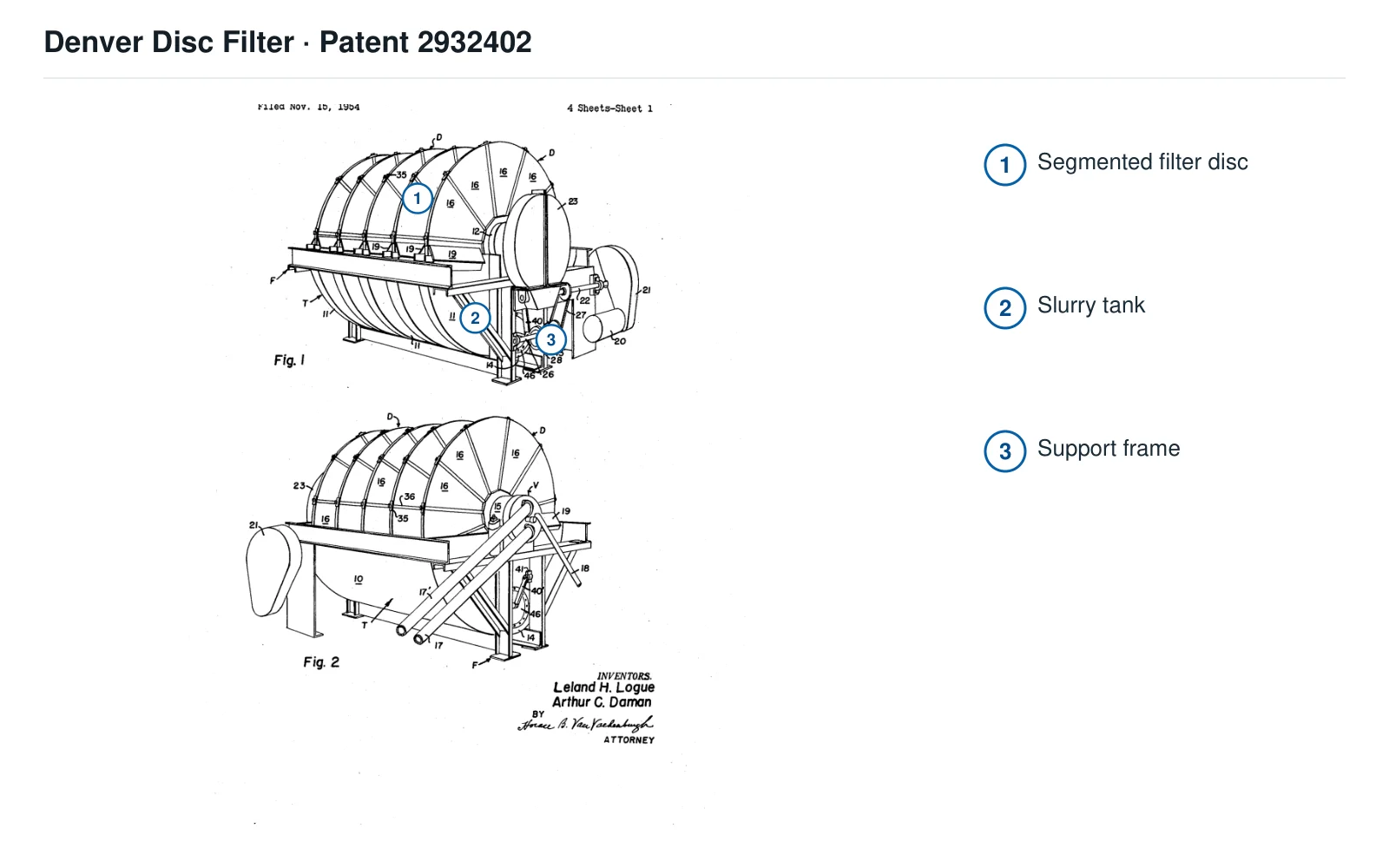
The numbers on the diagram correspond one to one with the rows below.
| No. | Component | Location | Applies to |
|---|---|---|---|
| 1 | Segmented filter disc | Segmented disc in Fig.1 | No commercial model (US2932402 patented design) |
| 2 | Slurry tank | Tank below filter discs | No commercial model (US2932402 patented design) |
| 3 | Support frame | Supporting frame in Fig.1 | No commercial model (US2932402 patented design) |
| Component |
|---|
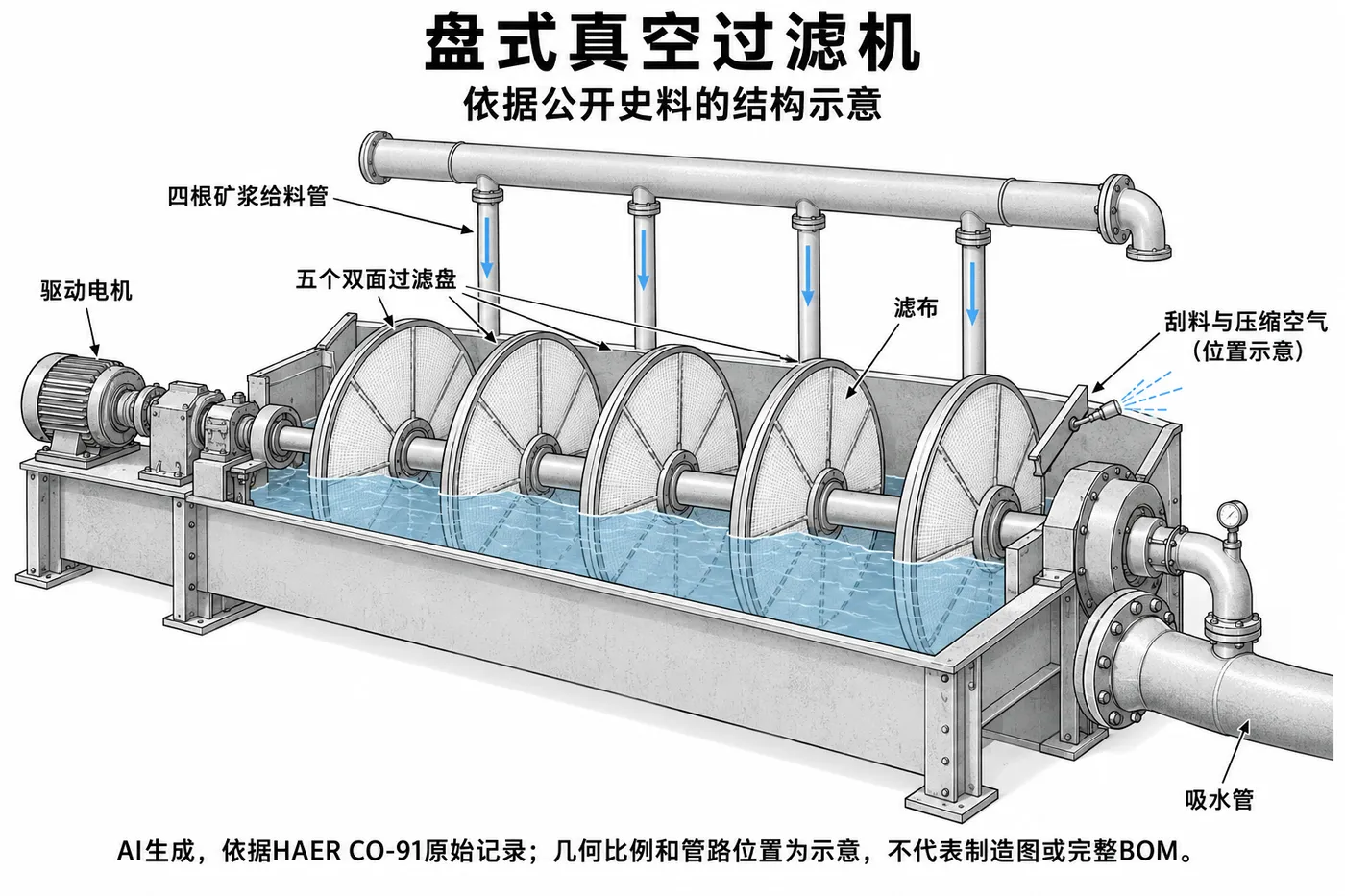
| Filter disc drive motor |
| Four vertical pulp feeding pipes and upper distribution pipes |
| Suction filter tube |
| Bearing housing |
| Filter cloth and cake discharge scraper |
| The filter disc supports the closed drum and horizontal shaft |
| Bearing set |
| Double-sided segmented filter cloth |
| Radial filtrate pipe and internal piping |
| Curved bead/nut clamp and radial strut |
| Filter switching valve |
| Vacuum/compressed air pipe set |
| Filter cake scraper |
| Reduction drive motor and pulley/shield |
| Worm gearbox and drive shaft |
| Countershaft chain/sprocket |
| Eccentric wheel/connecting rod and envelope bearing |
| Catenary flexible sealing diaphragm |
| Double slurry tank partition plate and diaphragm (optional double chamber design) |
| Five double-sided filter discs |
| Tank bottom reciprocating rod and pivot arm bracket |
| round/open hole/slotted/inclined/cup-shaped stirring plate (variant grouped components) |
| Diaphragm inner and outer clamping flange and pressure plate |
| Upper lever/auxiliary frame and open-hole flexible stirring piece (optional) |
| Upper shaft/chain belt/eccentric and up and down reciprocating rod (optional) |
Models with the same components are grouped together; select a group to open its component table.
| No. | Component | Location |
|---|---|---|
| 1 | Segmented filter disc and segmented block | Filtration face |
| 2 | Slurry tank body and filter disc tank well | Disk filter slurry container |
| 3 | Support frame | Tank body and main bearing support |
| Filter disc drive motor | Denver zinc filter unit described in 2005 filing; non-side Eimco component | |
| Four vertical pulp feeding pipes and upper distribution pipes | Denver zinc filter unit described in 2005 filing; non-side Eimco component | |
| Suction filter tube | Denver zinc filter unit described in 2005 filing; non-side Eimco component | |
| Bearing housing | Denver zinc filter unit described in 2005 filing; non-side Eimco component | |
| Filter cloth and cake discharge scraper | Denver zinc filter unit described in 2005 filing; non-side Eimco component | |
| The filter disc supports the closed drum and horizontal shaft | Filter disc rotating load | |
| Bearing set | Both ends of the horizontal axis of the filter disc | |
| Double-sided segmented filter cloth | Covered segmented block | |
| Radial filtrate pipe and internal piping | Filter disc section vacuum/compressed air/filtrate channel | |
| Curved bead/nut clamp and radial strut | External fixation of filter cloth and filter section support | |
| Filter switching valve | Filter disc vacuum and compressed air distribution | |
| Vacuum/compressed air pipe set | External connection for filtering and cake discharge | |
| Filter cake scraper | Discharge after the filter disc leaves the liquid level | |
| Reduction drive motor and pulley/shield | Filter disc low speed drive | |
| Worm gearbox and drive shaft | Filter disc shaft deceleration | |
| Countershaft chain/sprocket | Drive agitation eccentric | |
| Eccentric wheel/connecting rod and envelope bearing | Produces reciprocating stirring | |
| Catenary flexible sealing diaphragm | Reciprocating rod through groove wall seal | |
| Double slurry tank partition plate and diaphragm (optional double chamber design) | Figure 15 Two-chamber processing separation | |
| Five double-sided filter discs | Denver zinc filter unit described in 2005 filing; non-side Eimco component | |
| Tank bottom reciprocating rod and pivot arm bracket | Reciprocating stirring force transmission | |
| round/open hole/slotted/inclined/cup-shaped stirring plate (variant grouped components) | Reciprocating stirring at the bottom of the tank | |
| Diaphragm inner and outer clamping flange and pressure plate | Diaphragm to tank wall and rod fixation | |
| Upper lever/auxiliary frame and open-hole flexible stirring piece (optional) | Figure 16/17 Stirring variation without passing through the bottom of the tank | |
| Upper shaft/chain belt/eccentric and up and down reciprocating rod (optional) | Figure 18/19 Vertical stirring variant |
The Disc vacuum filter is also documented under these designations: Denver disc vacuum filter, Denver disk filter 4ft, Denver.
The Disc vacuum filter is listed under the Denver Equipment brand as: Disc vacuum filter. Period: 1958 1954. Status: Historical model.
28 components are recorded, including: Filter disc drive motor, Four vertical pulp feeding pipes and upper distribution pipes, Suction filter tube, Bearing housing, Filter cloth and cake discharge scraper, Slurry tank body and filter disc tank well, Support frame, The filter disc supports the closed drum and horizontal shaft and more. The full list with locations is in the components table on this page.
Model-specific components with their own page: Five double-sided filter discs, Tank bottom reciprocating rod and pivot arm bracket, round/open hole/slotted/inclined/cup-shaped stirring plate (variant grouped components), Diaphragm inner and outer clamping flange and pressure plate, Upper lever/auxiliary frame and open-hole flexible stirring piece (optional), Upper shaft/chain belt/eccentric and up and down reciprocating rod (optional) (6 in total).
Send us a drawing or sample and tell us the equipment model and part name.
Provide the equipment model, drawing for engineering review and quotation. If service life or wear is a concern, describe the operating conditions as well.
Or contact us directly: +86 156 3797 3199
zzx@anranst.com
ANRANST provides customers worldwide with engineering assessment, production at certified foundries to the customer technical requirements, quality control and finished-part delivery for custom wear parts and industrial spares, with scope to support other custom industrial parts.
We review mating surfaces and interface dimensions and assess material, heat treatment and manufacturing feasibility.
Material grades and heat-treatment processes are specified order by order, stated in the technical agreement and tracked through production.
Drawing confirmation, material and process control, production tracking, inspection and acceptance coordination.
We coordinate manufacturing, quality confirmation, packaging and delivery of complete finished parts in a workable, closed-loop supply process.
Provide the equipment brand, complete model and serial number, part name, part number or drawing number, drawing revision, quantity, material requirements and duty. If identifiers are unavailable, send photographs and key dimensions.
Submit an Enquiry