
01
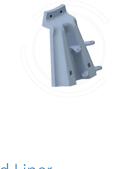
بطانة حلق التغذية
بطانة الحلق
يحمي مرتكز الدوران أو الحلق في نهاية التغذية من الصدمات والتآكل الناتج عن الملاط والخام وكرات الطحن. طابق الأقطار الداخلية والخارجية والطول والشفة وتوزيع الثقوب واتجاه الدوران وواجهة التغذية.
عرض تفاصيل الجزء →ابدأ بالقطر الاسمي لسلسلة SAG وأبعاد أسطوانة المشروع، ثم حدد أنظمة بطانات طرف التغذية والأسطوانة والأطراف والتفريغ، وتروس الإدارة والمواد ومتطلبات الرسومات والاستفسار.
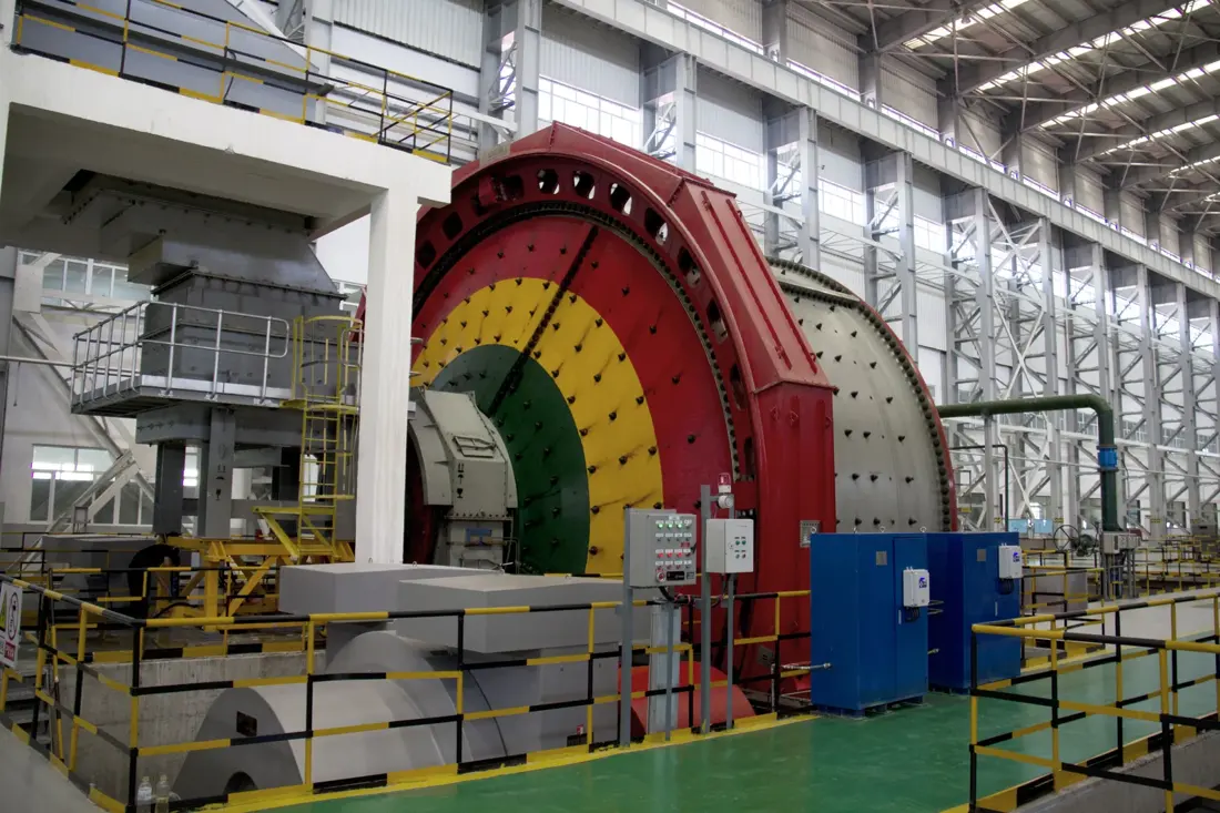
تتبع هذه الصفحة سلسلة SAG ذات القطر الاسمي وأبعاد المشروع المنشورة من CITIC HIC، مع مسارات لمواضع البطانة والمواد وأجزاء المحرك وفحوصات أرقام الرسم.
تحدد لاحقة الطراز القطر الاسمي لأسطوانة المطحنة. يختلف طول الأسطوانة والإدارة ونظام التفريغ وترتيب البطانات حسب المشروع، ويجب مطابقتها مع لوحة بيانات المشروع ورسم الترتيب العام والرسومات قبل التصنيع.
| سلسلة الطراز | القطر الاسمي للقذيفة | طول الأسطوانة حسب المشروع | الفحوصات المطلوبة قبل التصنيع |
|---|---|---|---|
| SAG-40 | 4,000 mm | طابق طول غلاف المطحنة للمشروع | لوحة البيانات والترتيب العام والتفريغ وتكوين الإدارة |
| SAG-45 | 4,500 mm | طابق طول غلاف المطحنة للمشروع | لوحة البيانات والترتيب العام والتفريغ وتكوين الإدارة |
| SAG-50 | 5,000 mm | طابق طول غلاف المطحنة للمشروع | لوحة البيانات والترتيب العام والتفريغ وتكوين الإدارة |
| SAG-55 | 5,500 mm | طابق طول غلاف المطحنة للمشروع | لوحة البيانات والترتيب العام والتفريغ وتكوين الإدارة |
| SAG-61 | 6,100 mm | طابق طول غلاف المطحنة للمشروع | لوحة البيانات والترتيب العام والتفريغ وتكوين الإدارة |
| SAG-67 | 6,700 mm | طابق طول غلاف المطحنة للمشروع | لوحة البيانات والترتيب العام والتفريغ وتكوين الإدارة |
| SAG-73 | 7,300 mm | طابق طول غلاف المطحنة للمشروع | لوحة البيانات والترتيب العام والتفريغ وتكوين الإدارة |
| SAG-80 | 8,000 mm | طابق طول غلاف المطحنة للمشروع | لوحة البيانات والترتيب العام والتفريغ وتكوين الإدارة |
| SAG-85 | 8,500 mm | طابق طول غلاف المطحنة للمشروع | لوحة البيانات والترتيب العام والتفريغ وتكوين الإدارة |
| SAG-88 | 8,800 mm | تتضمن أبعاد المشروع المنشورة 4,800 / 5,500 mm | المشروع ولوحة البيانات والترتيب العام وتكوين الإدارة |
| SAG-92 | 9,200 mm | طابق طول غلاف المطحنة للمشروع | لوحة البيانات والترتيب العام والتفريغ وتكوين الإدارة |
| SAG-98 | 9,800 mm | طابق طول غلاف المطحنة للمشروع | لوحة البيانات والترتيب العام والتفريغ وتكوين الإدارة |
| SAG-104 | 10,400 mm | تشتمل أبعاد المشروع المنشورة على 5,190 mm تقريبا | المشروع ولوحة البيانات والترتيب العام وتكوين الإدارة |
| SAG-110 | 11,000 mm | تتضمن أبعاد المشروع المنشورة 5,400 / 6,400 mm | المشروع ولوحة البيانات والترتيب العام وتكوين الإدارة |
| SAG-122 | 12,200 mm | طابق طول غلاف المطحنة للمشروع | لوحة البيانات والترتيب العام والتفريغ وتكوين الإدارة |
| SAG-128 | 12,800 mm | طابق طول غلاف المطحنة للمشروع | لوحة البيانات والترتيب العام والتفريغ وتكوين الإدارة |
| SAG-134 | 13,420 mm | طابق طول غلاف المطحنة للمشروع | لوحة البيانات والترتيب العام والتفريغ وتكوين الإدارة |
تتطابق الأرقام على المخطط مع الصفوف أدناه.
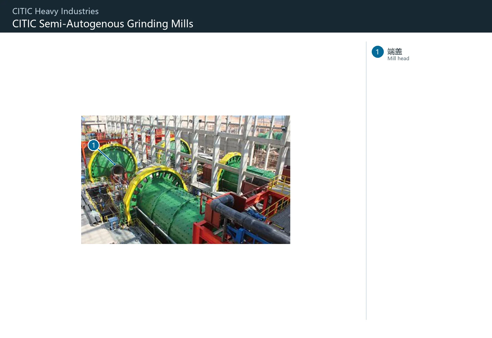
| الرقم | المكوّن | الموضع | ينطبق على |
|---|---|---|---|
| 1 | غطاء نهاية المطحنة | غطاء نهاية المطحنة الدائري الأخضر الظاهر في الخلف يسارا | مطحنة SAG لمشروع KSO; تعليق المشروع في الصفحة الرئيسية للموقع Ø8.8×4.8m |
يمتد النظام من حلق التغذية إلى رافعات الشحنة على الأسطوانة وبطانات الأطراف والشبكات وروافع تفريغ الملاط ومخروط التفريغ. تختلف الصدمات والتآكل الكاشط والتعرية بالملاط ومتطلبات المواد وعمليات تصنيعها حسب الموقع.
بطانة الحلق
يحمي مرتكز الدوران أو الحلق في نهاية التغذية من الصدمات والتآكل الناتج عن الملاط والخام وكرات الطحن. طابق الأقطار الداخلية والخارجية والطول والشفة وتوزيع الثقوب واتجاه الدوران وواجهة التغذية.
عرض تفاصيل الجزء →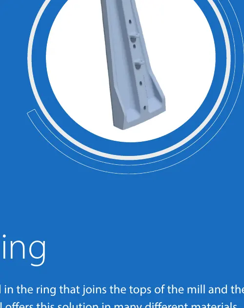
بطانة خارجية للرأس من جهة التغذية
يحمي الحلقة الخارجية ومنطقة الانتقال لرأس نهاية التغذية. طابق التجزئة والانحناء وموضع الحلقة الداخلية والخارجية وتوزيع الثقوب وواجهة الرافعة واتجاه الدوران.
عرض تفاصيل الجزء →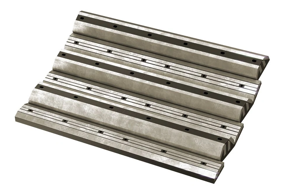
لوح رفع شحنة الطحن في الأسطوانة
يتم تركيبها على الهيكل الداخلي لرفع الخام وكرات الطحن والتحكم في مسارها. طابق الترتيب وارتفاع الرافعة والملف الجانبي وتباعد الفتحات وقطر الأسطوانة واتجاه الدوران.
عرض تفاصيل الجزء →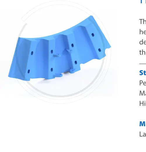
بطانة داخلية للرأس
يحمي الحلقة الداخلية لرأس الطاحونة ويتصل بالحلق أو الشبكة أو الرافعة. طابق موضع الحلقة والتجزئة والانحناء وتوزيع الثقوب واتجاه الدوران وواجهات الأجزاء المجاورة.
عرض تفاصيل الجزء →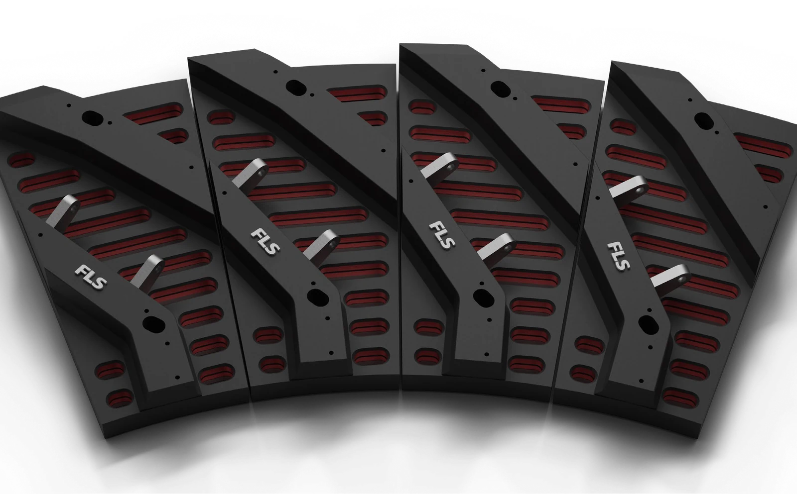
شبكة تصريف
يتحكم في مرور الملاط والجسيمات ذات الحجم الصحيح مع حماية طرف التفريغ. طابق شكل الفتحة، والمساحة المفتوحة، والتجزئة، والانحناء، وتوزيع الثقوب، واتجاه الدوران، وسجلات الانسداد أو التآكل.
عرض تفاصيل الجزء →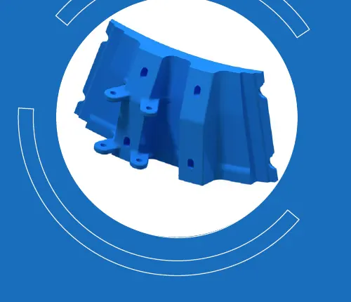
بطانة وسيطة
منطقة انتقالية بين البطانة النهائية ونظام التفريغ. طابق طبقة التثبيت، وموضع الحلقة الداخلية أو الخارجية، والانحناء، والتجزئة، وتوزيع الثقوب والعلاقة مع روافع تفريغ الملاط المجاورة.
عرض تفاصيل الجزء →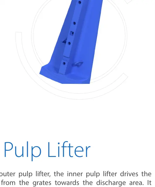
رافع التفريغ (ليفتر) للملاط
يوجه الملاط الذي يمر عبر الشبكة باتجاه نهاية التفريغ. طابق موضع الحلقة الداخلية أو الخارجية، واتجاه الريشة، والمقطع العرضي للقناة، واتجاه الدوران، وتوزيع الثقوب وسجلات الانسداد أو التآكل.
عرض تفاصيل الجزء →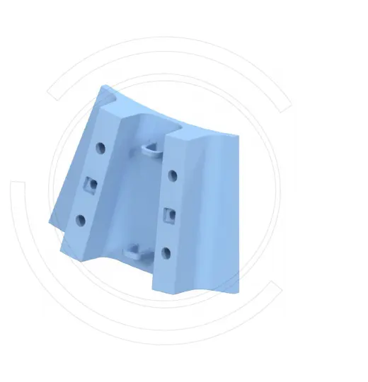
رافع تفريغ داخلي للملاط
تقع في الحلقة الداخلية لنظام رافع تفريغ الملاط بين الشبكة ومخروط التفريغ. طابق اتجاه الريشة والقناة والواجهات الحلقية الداخلية والخارجية واتجاه الدوران والارتفاع المثبت.
عرض تفاصيل الجزء →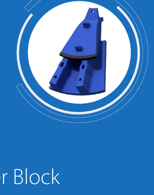
مخروط التفريغ
يوجه الملاط من الرافع إلى فتحة التفريغ. طابق زاوية المخروط والأقطار الداخلية والخارجية والطول والشفة وتوزيع الثقوب واتجاه الدوران وواجهة غلاف التفريغ.
عرض تفاصيل الجزء →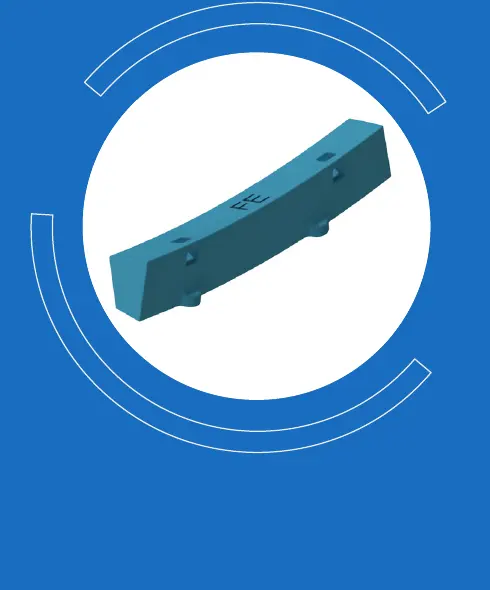
حلقة ملء
يملأ الحدود أو الفجوات الانتقالية في نظام البطانات ويحافظ على ترتيب البطانات. طابق طبقة الحلقة والمقطع العرضي والانحناء والطول وتوزيع الثقوب ومجموعة البطانات المجاورة.
عرض تفاصيل الجزء →يجب مطابقة زوج التروس معا من حيث الموديول وعدد الأسنان وزاوية الضغط واتجاه الحلزون والمسافة بين المركزين وخلوص التعشيق ونمط التلامس والمادة والمعالجة الحرارية ومتطلبات الفحص.
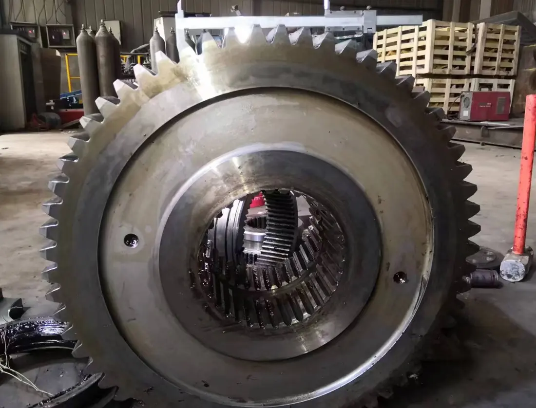
ترس حلقي / ترس حلقي
يتم تركيبه حول الهيكل أو الرأس ومتشابك مع الترس الصغير لنقل المحرك الرئيسي. طابق الموديول وعدد الأسنان، وزاوية الضغط، وزاوية الحلزون، والمفاصل المقسمة، والمسافة المركزية، ونمط التلامس.
عرض تفاصيل الجزء →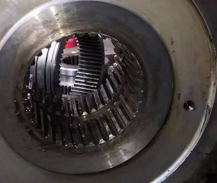
Pinion
يتزاوج مع الترس الحلقي لنقل مخرجات المحرك وعلبة التروس. طابق الموديول وعدد الأسنان، وزاوية الضغط، واتجاه الحلزون، وواجهة العمود، وخلوص التعشيق ونمط التلامس.
عرض تفاصيل الجزء →لا. قد يكون للمطاحن الموجودة في نفس سلسلة القطر الاسمي أطوال مشروع ومحركات وأنظمة تفريغ وترتيبات بطانة مختلفة. طابق المشروع ولوحة البيانات والترتيب العام والرسم ومراجعة الرسم.
لا. يجب أيضا مطابقة موضع التثبيت والترتيب والملف الجانبي وتوزيع الثقوب وارتفاع الرافع والتأثير والتآكل والخام واتجاه الدوران ومعالجة المواد ومتطلبات القبول.
قم بإرسال لوحة البيانات وقطر الغلاف × الطول والترتيب العام وموضع التثبيت وصور الأجزاء المستخدمة وتخطيط البطانة والأبعاد الحرجة لتقييم التحديد ومسح الأبعاد وجدوى التصنيع.
قم بتوفير الطراز الكامل وقطر الغلاف × الطول والرقم التسلسلي وتخطيط البطانات والرسومات وصور الأجزاء المستخدمة والمواد وظروف الخدمة. نقوم بتنسيق تحديد المعدات وتقييم المواد واختيار التصنيع ومراقبة الجودة وتسليم الأجزاء النهائية.
أو تواصل معنا مباشرة: +86 156 3797 3199
zzx@anranst.com
تقدّم ANRANST لعملائها حول العالم التقييم الهندسي والإنتاج في مسابك معتمدة وفق المتطلبات الفنية للعميل ومراقبة الجودة وتسليم القطع الجاهزة لقطع التآكل المخصّصة وقطع الغيار الصناعية، مع إمكانية دعم قطع صناعية مخصّصة أخرى.
نراجع أسطح التزاوج وأبعاد الوصلات، ونقيّم إمكانية التصنيع من حيث المادة والمعالجة الحرارية.
Material grades and heat-treatment processes are specified order by order, stated in the technical agreement and tracked through production.
تأكيد الرسم، ومراقبة المواد والعمليات، ومتابعة الإنتاج، والفحص، وتنسيق القبول.
ننسّق التصنيع وتأكيد الجودة والتغليف والتسليم للقطع الكاملة ضمن سلسلة توريد متكاملة وعملية.
Provide the equipment brand, complete model and serial number, part name, part number or drawing number, drawing revision, quantity, material requirements and duty. If identifiers are unavailable, send photographs and key dimensions.
أرسل استفساراً