
HIGmill Drive spares
العمود الرئيسي ومجموعة دعم الدوار
العمود الرئيسي ومجموعة دعم الدوار
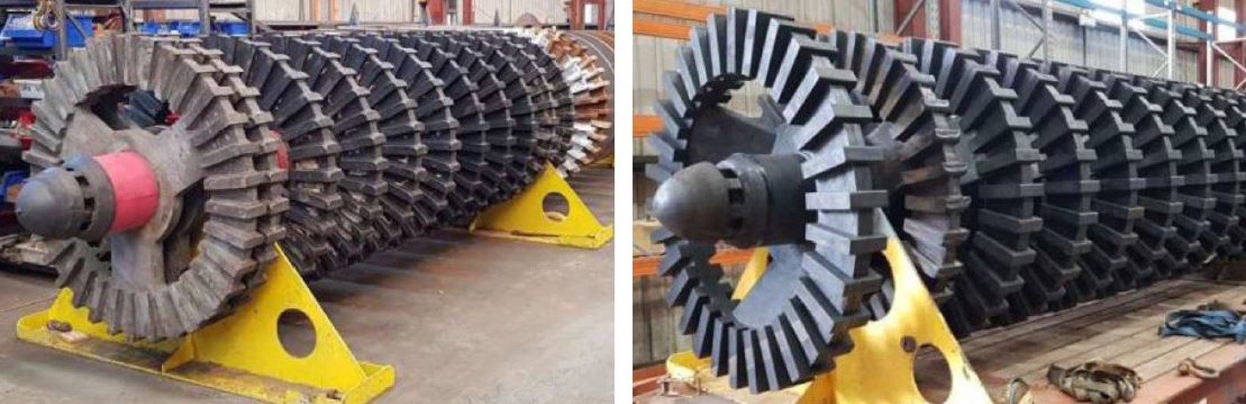
The HIGmill main shaft transmits torque from the top drive to each grinding rotor stage. Main shafts, sleeves, connecting parts and multistage rotor assemblies can be identified separately and supplied to drawings.
المعدات Metso / Swiss Tower Mills HIGmill
موقع التركيب Centre of the vertical mill body, from the top drive to the grinding stages
Main Loads Torque, bending, cyclic loads and assembly stresses
متطلبات التحديد Model, general arrangement drawing, main shaft drawing, interfaces and heat treatment
Part scopeIndividual Part Main shaft, sleeves, connecting parts or locking parts Assembly configuration Main shaft and multistage rotor support assembly Key accuracy requirements Coaxiality, runout, fits and surface roughness Inspection priorities Materials, heat treatment, UT/MT and dimensional reports
Identify the main shaft, protective parts and connecting parts separately
The main shaft carries loads and transmits torque. Shaft sleeves, coupling sleeves, keys, locking parts and rotor supports are separate mating parts. Specify whether the RFQ covers an individual shaft, mating parts or a complete assembly with multistage rotors.
Manufacturing review covers overall length, shaft diameters, coaxiality, runout, rotor interfaces, upper drive interface, surface condition, material, heat treatment, nondestructive inspection and dynamic balance requirements.
Functional zones
Manufacturing priorities by main shaft zone
The installed main shaft drawing governs the actual shaft sections and interfaces.
Upper drive interface
Check the connection, key or spline arrangement, fit dimensions, torque transmission and surface hardness requirements.
Bearing and seal journals
Control dimensional tolerances, roundness, roughness, wear repair limits and seal running surfaces.
Grinding rotor mounting sections
Check rotor location at each stage, spacing, connections, axial locking and assembly balance.
المواد والعمليات
Coordinate alloy steel selection, forging and heat treatment
Specify the grade against the drawing. Material selection must satisfy strength, toughness, fatigue, hardenability, dimensional stability and site repair requirements together.
Alloy Steels for Drive Parts An initial material option for torque-transmitting and load-bearing shafts, subject to confirmation of shaft diameter, loads, heat-treated section size and fatigue requirements. Chromium-Molybdenum Alloy Steel For forgings requiring higher hardenability, strength, toughness and dimensional stability. The drawings and technical agreement govern composition, forging ratio and heat treatment.
Models and drawing references
Applicable HIGmill configurations
Main shafts vary with power, chamber volume, shell diameter and grinding-stage configuration.
| HIGmill Model | Key identification details | Drawing Number / Part Number |
|---|---|---|
| HIG3500/23000 | Check the 3,500 kW drive, grinding-stage count, shaft diameter and rotor interfaces | Confirm against the serial number, main shaft drawing and assembly drawing |
| HIG500/4000 | Check the 500 kW configuration, shaft sections and site modification version | Confirm against the serial number, main shaft drawing and assembly drawing |
| HIG25 / HIG5 | Pilot and test configurations; do not infer dimensions from industrial units | Confirm against the nameplate and test equipment drawings |
| Other industrial HIGmill models | Provide power, chamber volume, general arrangement drawing and main shaft interface data | Record OEM drawing references, third-party references and drawing revisions |
Match third-party drawing references to the specific HIGmill model, main shaft version, drawing revision and key dimensions.
RFQ information
Main shaft identification information
Used shafts can support dimensional surveys, but wear and deformation must be assessed. Do not reproduce failed dimensions directly.
تحديد المعدات
الشركة المصنعة الأصلية والطراز الكامل والرقم التسلسلي ولوحة البيانات.
Shaft supply scope
Individual main shaft, mating parts or complete rotor assembly.
Drawing references and drawings
OEM references, third-party references, drawing revisions and assembly relationships.
الأبعاد الرئيسية
Overall length, shaft diameters, interfaces, fits, tolerances and roughness.
المواد والعمليات
Current material, forging, heat treatment and surface hardening records.
Failure information
Wear, cracks, bending, vibration and repair history.
الأجزاء والمعدات ذات الصلة
المعدات, rotors and support system
Check the main shaft together with the installed model, grinding rotors, bearings and seal configuration.
Request a HIGmill العمود الرئيسي Proposal and Quotation
Provide the model, drawing reference, main shaft drawing, used-part dimensions, material and failure information for forging, machining, inspection and delivery review.
خدمات صنع في الصين
من التقييم الفني إلى تسليم المنتج بالكامل
توفر شركة ANRANST للعملاء العالميين تقييمات هندسية، واختيار التصنيع الصيني، ومراقبة الجودة، وتسليم الأجزاء النهائية لقطع الغيار الصناعية المقاومة للتآكل حسب الطلب، ويمكنها أيضًا دعم قطع الغيار الصناعية الأخرى حسب الطلب.
مراجعة الرسومات والهندسة
قم بمراجعة أسطح التزاوج وأبعاد الواجهة، وقم بتقييم جدوى المواد والمعالجة الحرارية والتصنيع.
تحديد المادة والمعالجة الحرارية
تُحدَّد درجات المواد وعمليات المعالجة الحرارية لكل طلب على حدة، وتُثبَّت في الاتفاقية الفنية وتُتابَع أثناء الإنتاج.
ضبط الجودة
يشمل ذلك تأكيد الرسم، ومراقبة المواد والعمليات، وتتبع الإنتاج، وتنسيق عمليات الفحص والقبول.
تسليم المنتج النهائي
تنظيم عمليات التصنيع والتحقق من الجودة والتعبئة والتغليف وتسليم المنتجات النهائية الكاملة لتشكيل حلقة إمداد قابلة للتنفيذ.
قم بتزويدنا بالنماذج الحالية، والرسومات، وأرقام الرسومات، وأرقام الأجزاء، والمواد، أو معلومات ظروف التشغيل، وسنقوم بتحديد التحقق الفني ومسار التوريد وفقًا لذلك.
إرسال طلب