
HIGmill Custom Structural Spares
Split Mill Bodies and Structural Parts
Split Mill Body and Structural Components
HIGmill uses a flanged split body to reduce maintenance space requirements. This page covers drawing review, manufacturing quality control and finished-part delivery for body sections, flanges, stator and liner interfaces, supports and connections.
Equipment Metso / Swiss Tower Mills HIGmill
Installation Position Vertical grinding chamber, flanged sections and support connections
Main requirements Pressure resistance, stiffness, coaxiality, weld integrity and sealing reliability
Identification requirements Model, mill body general arrangement, section drawings and stator/liner interfaces
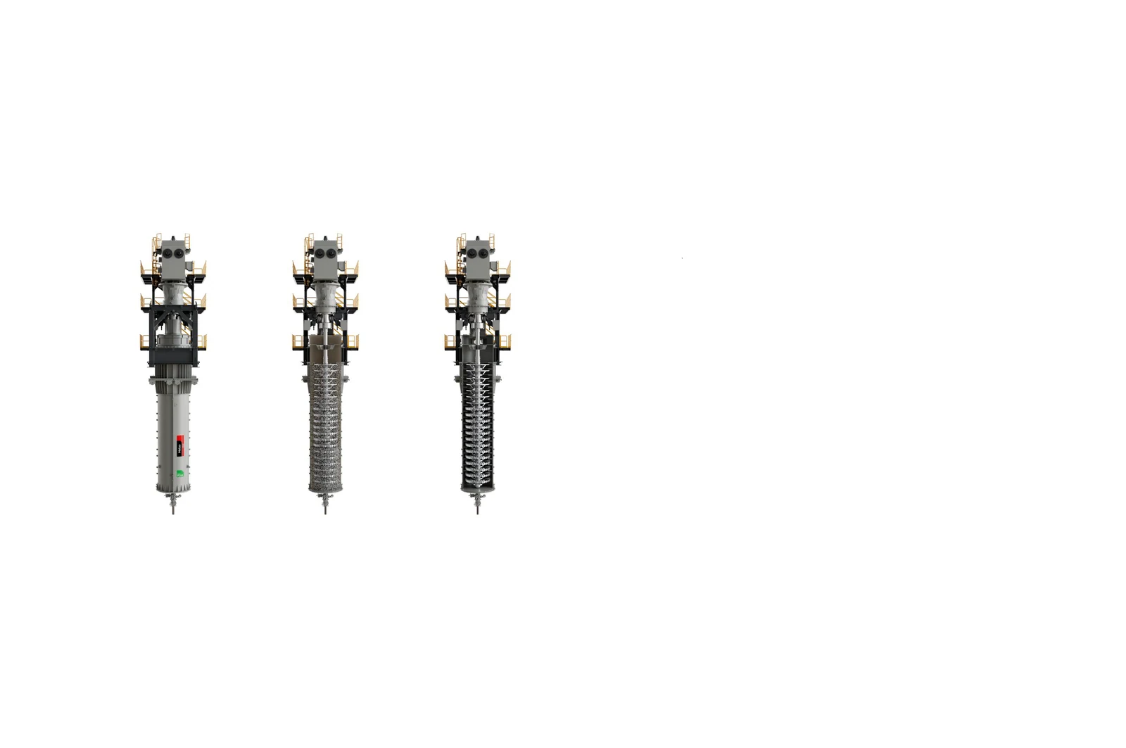
Structural scopeIndividual Part Body sections, flange rings, supports or interface parts Assembly configuration Split body with stator and liner mounting system Key accuracy requirements Diameter, roundness, coaxiality, flanges and hole patterns Quality priorities Materials, welding, NDT, dimensions and pressure/leak tests
The mill body requires more than a rolled and welded shell
The body must meet grinding chamber geometry, stator and liner mounting, flanged section, support, feed and discharge, maintenance and sealing requirements. Manufacture requires a complete general arrangement, interfaces and acceptance criteria, not outside diameter and height alone.
Identify the complete body, individual sections, flange rings, supports, interface mounts and connecting parts separately for each project. When surveying used parts, distinguish design dimensions from welding distortion and service wear.
Structural zones
Control sections, flanges and internal interfaces separately
Define all datums in the manufacturing drawings and inspection plan.
Body sections and flanges
Control rolled-section roundness, flange flatness, hole-pattern positions, section interchangeability and site assembly clearances.
Stator and liner interfaces
Control mounting datums, fastening holes, local reinforcement, curvature and coaxial alignment of adjoining grinding stages.
Support and nozzle structures
Check load paths, welds, reinforcing plates, feed and discharge interfaces, maintenance and lifting requirements.
Materials and Processes
Coordinate steel plate, welding and nondestructive inspection
The drawings and technical agreement govern steel grade, plate thickness, welding consumables, preheat, post-weld heat treatment and inspection coverage.
Structural and Quenched and Tempered Steel Plate Select materials for pressure resistance, weldability, low-temperature toughness, thickness and interface loads. A wear plate designation does not replace structural calculations. Welding and Repair Processes Control joint preparation, welding consumables, preheat, interpass temperature, distortion, post-weld treatment and inspection requirements such as UT/MT/PT.
Models and drawing
Mill bodies vary with volume and diameter
The equipment series name is insufficient to identify body sections and interfaces.
| HIGmill Model | Key identification details |
|---|---|
| HIG3500/23000 | 23,000 L mill body; check sections, stator stage count, supports and nozzles |
| HIG500/4000 | 4,000 L mill body; check diameter, flanges, hole patterns and site layout |
| HIG25 / HIG5 | Test equipment; construction differs from industrial mill bodies |
| Other industrial HIGmill models | Provide chamber volume, diameter, general arrangement, interfaces and maintenance revision |
Match third-party mill body drawing to the equipment serial number, volume, diameter, sections, material, welding class and drawing revision.
RFQ information
Mill body and structural part identification information
Start with the general arrangement drawing and site measurements where necessary so engineers can determine the manufacturing details required.
Equipment identification
OEM, model, serial number, volume and nameplate.
Supply scope
Complete mill body, individual section, flange, support or interface part.
General arrangement and interfaces
Diameter, height, sections, flanges, hole patterns, nozzles and supports.
Internal assembly
Stator rings, liners, fasteners and grinding-stage datums.
Materials and welding
Steel plate, welding consumables, procedure qualification, heat treatment and inspection requirements.
Site condition
Deformation, cracks, corrosion, leaks and repair history.
Related Equipment and Parts
Equipment, liners and structural manufacturing
Check the mill body and internal wear system against the same assembly datums.