
HPGR tungsten carbide studs
HPGR Studs
Cemented Carbide Wear Parts for HPGR Roller Surfaces
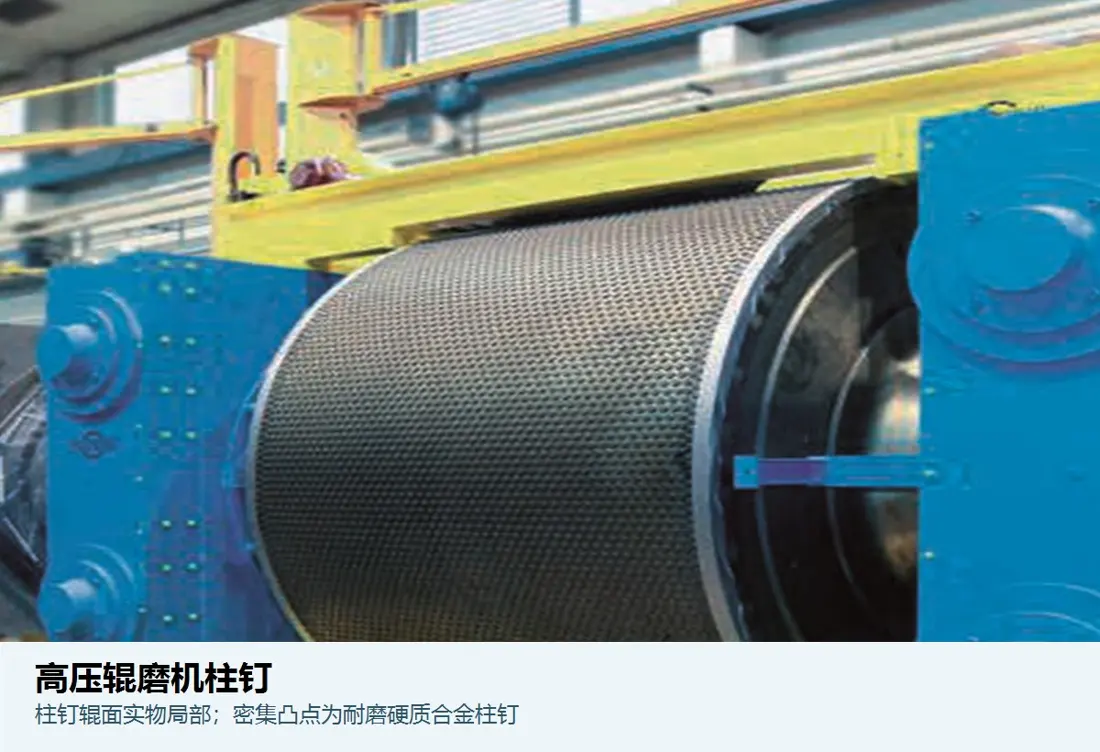
Studs are fitted into HPGR or roller press surfaces and withstand abrasion and local impact in the high-pressure material bed. Correct supply requires checks of the stud, mounting hole, roller substrate, layout and installed machine model.
Main ProductsTungsten Carbide Studs / Roller Studs
Installation PositionHPGR Working Roll Surface
Main LoadsHigh-pressure material bed, abrasion, local impact and cyclic compression
Identification requirementsOEM, full model, roll identification, drawing and measurements in service
Part scopeStud Geometry Head, shank diameter, length, radii, end face and material Mounting Interface Hole diameter and depth, interference or retention method, and substrate condition Stud Layout Rows, spacing, density, edge arrangement and protrusion Condition in Service Wear, chipping, pull-out, looseness and surrounding substrate wear
Individual studs, roller substrates and complete roller surfaces have different supply requirements
This page covers individual studs. Drilled roller sleeves, tyres, roller substrates, studded roller assemblies, roll shafts and bearing systems are separate products and must be identified separately in an inquiry.
The stud-to-roller fit determines resistance to pull-out. Stud protrusion and layout influence formation of the autogenous protective layer. A stud photograph alone cannot establish interchangeability.
Individual Stud Details
HPGR Stud Specifications
Use the same stud specification page from the general catalogue or the OEM equipment listing.
HPGR Roll Studs
Check individual geometry, sintered carbide material, roller mounting holes, stud positions, failure condition and known drawing.
Studded Roller Surface Assembly
A related assembly with a separate supply scope. Provide roller diameter and width, roll identification, surface design, hole pattern and assembly drawings.
Edge and Centre Positions
Wear, pressure and stud layout can vary across the roller surface. Confirm each position against original drawings or measurements in service before specifying a common size.
Materials and Properties
Studs made from sintered tungsten carbide
Tungsten carbide studded roller surfaces require a hard phase, binder, microstructure and strength suited to the actual operating conditions.
WC-Co Cemented Carbide The tungsten carbide hard phase provides wear resistance, while the metallic binder provides toughness. Select the grade together with impact conditions, particle size, moisture and roller fit.Steel Roller Substrate The roller sleeve or substrate supports the studs and retains their mounting holes. Assess the substrate material, hole wall condition and fitting process together with the studs. Autogenous Protective Layer Material can accumulate between protruding studs to form a protective layer that reduces direct wear of the roller substrate. Its formation depends on both feed properties and roller geometry. Different from Steel Fasteners HPGR working studs are not weld studs, threaded studs, dowel pins or hopper fasteners; ordinary steel fastener grades do not apply.
Locations and Failure Modes
Use roller condition to prioritise replacement and inspection
Use the following categories to document site conditions. Dimensions and repair decisions depend on machine records, measurements and the agreed technical specification.
| Location / Symptom | Priority checks | Possible Effects |
|---|---|---|
| High-Load Centre Zone | Remaining stud height, fractures, missing studs, layout and material distribution | Protective layer stability, roller wear and pressure distribution |
| Edge Zone | Edge arrangement, uneven wear, feed distribution and lateral confinement | Local wear, edge effects and uneven loading |
| Stud Pull-Out or Loosening | Mounting holes, fit, substrate cracks, retention process and tramp material impacts | Enlarged holes, increased loading on adjacent studs and roller surface damage |
| Stud Chipping or Fracture | Microstructure, defects, transition radii, tramp metal and transient impact | Reduced effective height, fragments in the material bed and spreading local damage |
| Recessed Surrounding Substrate | Protective layer, differences in stud height, material properties and roller repair history | Reduced retention and changes in roller profile |
Inquiries and Quality Control
Information Required before Stud Supply
Provide the drawing, sample or customer drawing, with its revision, to identify the required stud.
Equipment identification
OEM, full model, serial number, roll or sleeve identification, and left or right roll position.
Drawings and References
Stud and roller assembly drawing, customer model details, revision and modification history.
Key dimensions
Overall length, section diameters, head, radii, mounting hole, protrusion and positional tolerances.
Material Data
Current grade, density, hardness, microstructure, transverse rupture strength or other agreed properties.
Roller Surface Condition
Wear scans, missing stud distribution, substrate recesses, hole wall damage and repair history.
Operating conditions
Ore, particle size, moisture, abrasiveness, tramp material, pressure, speed and service life.
Lining selection: Metso HRC literature describes studded tungsten carbide roller surfaces. KHD Roller Press literature describes sintered tungsten carbide studs fitted into the roller surface, with ground material forming an autogenous protective layer between them. Installed dimensions and supply scope follow the drawings and agreed technical specification. Metso HRC HPGR · KHD Roller Press
Related Equipment and Parts
Equipment, Media and Materials
Find the same stud specification from the OEM or general equipment page.
HPGR High Pressure Grinding Rolls General equipment details for roller surfaces, edges, hydraulics and drives. Stud / Roller Stud Details Drawing or sample, dimensions, materials, installed models and RFQ requirements. Cemented Carbide Materials Carbide hard phases, binders, properties and inspection requirements. OEM Brands & Models Identify parts by brand, series and full installed model.