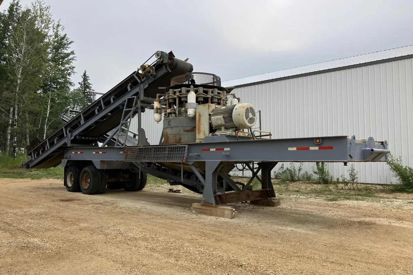
Roller bearing Cone crusher

Roller bearing cone crusher · 1950 · 4 models

ElJay Roller bearing Cone crusher – Roller bearing cone crusher
ElJay Roller bearing Cone crusher – Roller bearing cone crusher (2)
ElJay
ElJayBrand
Roller bearing cone crusherEquipment type
1950Period
Historical modelStatus
ElJay

Models and Historical Names in This Series

Select a model to jump to its component table; former and renamed designations are listed under “Historical names / renamings”.

ModelHistorical names / renamingsPeriodComponents
ElJay Rollercone Classic roller bearing cone crusherRollercone Classic 36; Rollercone Classic 45; Rollercone Classic 54; Rollercone Classic 60; Rollercone Classic 66; ElJay Rollercone Classic; RC45-I Classic; RC54-I Classic; Rollercone Classic RC36; Rollercone Classic RC45; Rollercone Classic RC54; Rollercone Classic RC60; Rollercone Classic RC66; RC36 Standard - Coarse; RC36 Standard - Medium; RC36 Fine Head - Coarse; RC36 Fine Head - Fine; RC45 Coarse Chamber; RC45 Medium-Fine Chamber; RC45 Fine Chamber; RC45 Extra-Fine Chamber; RC54 Coarse Chamber Enlarged Feed; RC54 Coarse Chamber; RC54 Medium Chamber; RC54 Medium Fine Chamber; RC54 Fine Chamber; RC54 Extra Fine Chamber; RC60 Standard - Coarse; RC60 Standard - Medium Fine; RC60 Fine Head - Coarse; RC60 Fine Head - Fine; RC66 Standard - Coarse; RC66 Standard - Medium; RC66 Standard - Medium-Fine; RC66 Fine Head - Extra Coarse; RC66 Fine Head - Coarse; RC66 Fine Head - Fine; RC66 Fine Head - Extra-Fine195064
ElJay Rollercone II roller bearing cone crusherRollercone II; ElJay Rollercone II; RC45-II; RC54-II; Rollercone II RC45II; Rollercone II RC54II199060
Cedarapids RC45III (successor of ElJay Rollercone technology)Cedarapids RC45III2012-0341
ElJay Sand ConeElJay Sand cone; ElJay Sand Cone 5420252
ElJay

Numbered Components

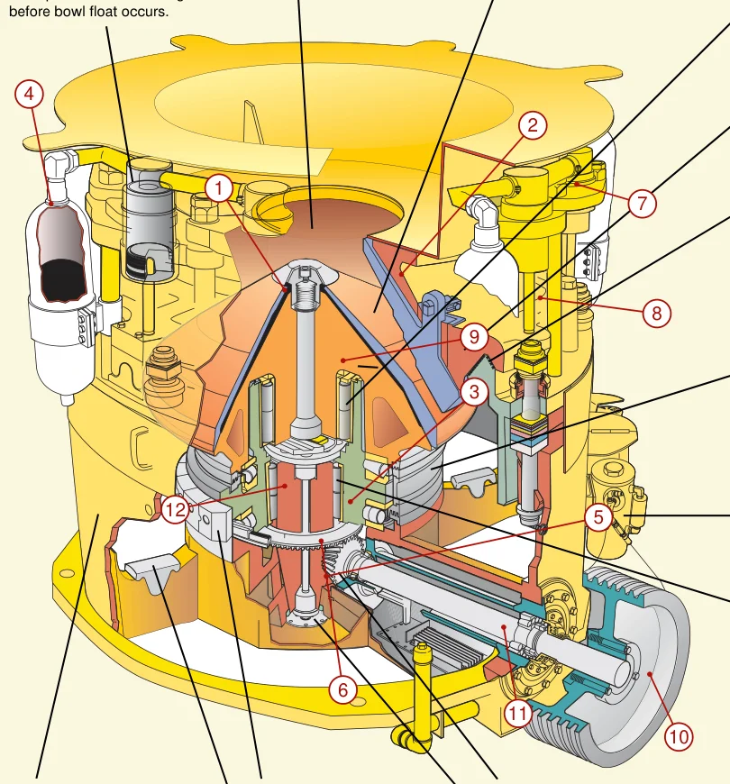
The numbers on the diagram correspond one to one with the rows below.

No.ComponentLocationApplies to
1MantleCrushing surface on the cone headRollercone Classic;Rollercone II
2Bowl linerInner crushing surface of the bonnetRollercone Classic;Rollercone II
3Roller bearingCentral roller support below the cone headRollercone Classic;Rollercone II
4Nitrogen bladder accumulatorAccumulator adjacent to the tramp-relief cylinderRollercone Classic;Rollercone II
5PinionInner end of the pinion shaftRollercone Classic;Rollercone II
6Bevel gearDrive gear below the wedge plateRollercone Classic;Rollercone II
7BonnetUpper bonnetRollercone Classic;Rollercone II
8Bonnet supportBonnet support above the base frameRollercone Classic;Rollercone II
9Cone headCone head behind the mantleRollercone Classic;Rollercone II
10Drive sheaveSheave at the outer end of the pinion shaftRollercone Classic;Rollercone II
11Pinion shaftHorizontal pinion shaft through the baseRollercone Classic;Rollercone II
12Wedge plateInclined wedge plate under the cone headRollercone Classic;Rollercone II
Other Components · 28 items
Component
Exhaust outlet adjustment gasket
Thrust Bearing — Upper/lower thrust roller bearing
Lubricating oil pump and filter
Non-contact labyrinth seal
Manual feed hopper
Bowl Liner / Concave — Manual bowl liner
Mantle / Head Liner — Manual Moving Cone Liner
Manual compression cylinder
Manual outlet adjustment bolt
Manual upper/lower adjustment shim set
Manual clamping ring
Thrust Bearing — Manual Thrust Bearing
Manual Radial Bearing
Manual overrunning clutch
Manual Brake Shaft
Manual Gasket Guard
Manual Over-Iron Pressure Relief Cylinder
Manual Over-Iron Pressure Relief Manifold
Manual plastic backing
Manual moving cone fastening nut and washer
Manual nut cover and cover bolt
Manual sponge rubber strip
Manual upper assembly O-ring
Manual cone head compression bolt
Manual clamping accumulators and valves
Manual Clamping Split Couplings
Manual Adjustment of Jacking Cylinder
Manual Adjustment Jacking Manifold Block
ElJay

Components by Model

Models with the same components are grouped together; select a group to open its component table.

ElJay Rollercone Classic roller bearing cone crusher64 items
No.ComponentLocationPart / drawing no.
3Roller bearingCentral support system02-540-155-7000 / 02-540-156-0000
4Nitrogen bladder accumulatorHydraulic overload release system02-450-071-0000 / 02-360-330-0000
Mantle / Head LinerCrushing cone head02-360-022-0003 / 02-360-363-7001 / 02-360-022-7011 / 02-450-022-0004
Bowl Liner / ConcaveBowl liner02-360-023-0010 / 02-360-386-0010 / 02-360-364-7000 / 02-360-023-7010
Exhaust outlet adjustment gasketHydraulic vertical adjustment and locking place02-450-551-0000 / 02-450-552-0000 / 02-450-553-0000 / 02-450-554-0000
Thrust Bearing — Upper/lower thrust roller bearingBetween wedge plate and machine base02-540-155-7000 / 02-540-156-0000
PinionDrive countershaft02-540-032-0020
Drive Gear — Bevel gearWedge plate rotation drive02-540-005-0020
Lubricating oil pump and filterSelf-contained machine base oil sump external oil supply circuit00-873-000-0000 / 00-871-000-0010
Non-contact labyrinth sealBetween the rotating structure and the machine base
Manual feed hopperFig.3-1/3-2, covering RC45-I/II and RC54-I/II02-540-010-7010
Manual upper bowl frame bonnetUpper load-bearing part, Fig.3-1; not inferred from the complete machine hood02-540-009-7004
Manual bowl frame supportFig.3-1 bonnet support02-540-012-0021
Bowl Liner / Concave — Manual bowl linerFig.3-1/3-2; coarse/fine cavity is optional02-360-023-0010 / 02-360-386-0010 / 02-360-364-7000 / 02-360-023-7010
Mantle / Head Liner — Manual Moving Cone LinerFig.3-1/3-2; coarse/fine cavity is optional02-360-022-0003 / 02-360-363-7001 / 02-360-022-7011 / 02-450-022-0004
Manual cone headFig.3-1/3-2; Do not put the manganese steel lining material on the cone head02-540-013-7030
Manual compression cylinderFig.3-1 and clamping system; 45/54 quantities vary02-450-345-0022 / 02-450-343-0012
Manual outlet adjustment boltClamping adjustment; RC45 eight groups, RC54 twelve groups, not all sizes have the same number02-540-048-7023
Manual upper/lower adjustment shim setExhaust port adjustment; there are differences in early sequence configurations02-450-551-0000 / 02-450-552-0000 / 02-450-553-0000 / 02-450-554-0000
Manual clamping ringFig.3-1 and clamping system02-540-044-0003
Manual drive pulleyFig.3-1 and Appendix D; OCR Shieve is based on image and text sheave
Manual pinion shaftFig.3-1; The specific alloy grade is not included02-600-033-0010
Thrust Bearing — Manual Thrust BearingFig.3-1; not equivalent to all conical copper sleeves02-540-155-7000 / 02-540-156-0000
Manual Radial BearingFig.3-1 rollercone support02-540-077-0000 / 02-540-021-0000
Manual overrunning clutchFig.3-1 overrunning clutch, braking mechanism association02-540-100-0010
Manual Brake ShaftFig.3-1 brake shaft02-540-099-0007
Manual wedgeFig.3-1 wedge plate; material not specified02-540-001-0006
Manual Gasket GuardFig.3-1 shim guard02-540-196-0005
Manual Over-Iron Pressure Relief CylinderFig.3-1 tramp relief cylinder02-540-504-0010 / 02-540-058-0020
Manual Over-Iron Pressure Relief ManifoldFig.3-1 and hydraulic system02-540-123-0010
Manual plastic backingFig.3-2 Behind the liner02-360-225-0000 / 45590-525-02
Manual moving cone fastening nut and washerFig.3-2 and Section 6; the original text is left-handed, and the dimensions will be checked one by one.02-540-014-8500
Manual nut cover and cover boltLiner retention in Fig.3-2
Manual sponge rubber stripFig.3-2 and Appendix C, lining assembly assistance
Manual upper assembly O-ringFig.3-2 and Appendix C, the specific elastomer is not included
Manual cone head compression boltFig.3-2 head hold-down bolt02-540-319-8500
Manual clamping accumulators and valves3-section clamping circuit, non-overload accumulator mixed weighing02-360-330-0000
Manual Clamping Split Couplings3-section split coupler
Manual Adjustment of Jacking Cylinder3 sections adjust jack cylinder/ram02-450-346-0001
Manual Adjustment Jacking Manifold Block3-section adjustment hydraulic circuit02-450-315-0000
Manual clamping cylinder manifold valve3-section clamping hydraulic circuit
Manual Overload AccumulatorSection 3/10, do not apply the clamping circuit parameters02-450-071-0000
Manual air release valve and rotation limitIron passing/adjustment system, internal BOM is not decomposed02-540-284-0040
Manual Immersion Oil Heater and Thermostat4-23, bottom of fuel tank; cooling fin material is limited to this part02-540-137-0010
Manual replaceable lubrication filter elementAppendix C oil change accessories, check according to the filter of this machine
RC54 Enlarged Feed bowl frameEnlarged Feed Bowl for Coarse/Medium cavity tableT191676 / T191685
Mantle / Head Liner — RC54 HD moving cone linerOriginal Classic cavity table HD Mantle optionT191701
Anti-rotation braking mechanismmain shaft bottom clutch/braking system02-450-098-0014 / 02-540-362-0007
Hydraulic adjustment gasket setUpper/lower gasket stack and locking ring position02-450-551-0000 / 02-450-552-0000 / 02-450-553-0000 / 02-450-554-0000
Anti-rotation brake assemblyBrake shaft, overrunning clutch and shear bolt location02-450-098-0014 / 02-540-362-0007
Manual Lifting Equipment and Paired RiggingAppendix C general requirements, not a complete kit proprietary to the manufacturer
Manual Field Installation Spirit LevelAppendix C Portable unit on-site installation tools
Manual Portable Hydraulic Pump with Quick CouplerAppendix C installation package; the quick connector is clearly provided with the machine, and the pump is not supplied with the label.01-224-005-0260
Manual comes with hexagonal wrenchAppendix C and maintenance text; tooling number will not be transcribed02-540-287-0000
Manual supplied with cone nut wrenchAppendix C Changing cone lining tool; not suitable for all cones02-540-320-8000
Manual Bowl Liner Removal Press and Steel Ring/BeamAppendix C; The press is required when the liner is difficult to remove, and is not included as standard.
Manual steel rod punchAppendix C Bowl Liner/Moving Cone Liner Maintenance Tools
Materials for manual lifting lugsAppendix C maintenance materials; no production operation steps are output
Manual Accumulator Charging Gauge AssemblyAppendix C, 0-20000kPa range; not the pressure setting value02-360-547-0000
Manual Nitrogen Precharge Pressure GaugeAppendix C pre-charge measurement; check specific connectors machine by machine
Manual nitrogen bottle and maintenance hoseAppendix C, pressure relief system maintenance consumables/tools, are not included with each machine before leaving the factory.
Manual Oil Sample Needle Assembly and Sample BottleAppendix C Oil Sampling Tool
Manual Pulley Groove Gauge and Belt Tension TesterAppendix D Wear/Tension Measurement Tool; No supplier tooling number is recorded
Automatic cold weather lubrication circulation kit (option)4-23, lubricating oil circulation at regular intervals; not standard equipment on all old machines
ElJay Rollercone II roller bearing cone crusher60 items
No.ComponentLocationPart / drawing no.
1Mantle / Head LinerCrushing cone head02-450-022-0004 / 02-450-527-8000 / 02-540-022-0003 / 02-540-527-8000
2Bowl Liner / ConcaveBowl liner02-450-023-0010 / 02-450-386-0000 / 02-450-528-8000 / 02-450-529-8000
5PinionDrive countershaft02-450-032-0100
6Drive Gear — Bevel gearWedge plate rotation drive02-450-005-0100
7Manual upper bowl frame bonnetUpper load-bearing part, Fig.3-1; not inferred from the complete machine hood02-450-009-0050
8Manual bowl frame supportFig.3-1 bonnet support4500-500-59
9Manual cone headFig.3-1/3-2; Do not put the manganese steel lining material on the cone head02-450-013-0008
10Manual drive pulleyFig.3-1 and Appendix D; OCR Shieve is based on image and text sheave06M24-001-01
11Manual pinion shaftFig.3-1; The specific alloy grade is not included02-450-033-0010
12Manual wedgeFig.3-1 wedge plate; material not specified4500-500-42
Thrust Bearing — Upper/lower thrust roller bearingBetween wedge plate and machine base02-450-156-0000 / 02-450-155-7000
Lubricating oil pump and filterSelf-contained machine base oil sump external oil supply circuit00-871-000-0400 / 00-873-000-0000 / 1503-022-14
Non-contact labyrinth sealBetween the rotating structure and the machine base
Manual feed hopperFig.3-1/3-2, covering RC45-I/II and RC54-I/II02-450-010-8040
Bowl Liner / Concave — Manual bowl linerFig.3-1/3-2; coarse/fine cavity is optional02-450-023-0010 / 02-450-386-0000 / 02-450-528-8000 / 02-450-529-8000
Mantle / Head Liner — Manual Moving Cone LinerFig.3-1/3-2; coarse/fine cavity is optional02-450-022-0004 / 02-450-527-8000 / 02-540-022-0003 / 02-540-527-8000
Manual compression cylinderFig.3-1 and clamping system; 45/54 quantities vary02-450-345-0022 / 02-450-343-0012
Manual outlet adjustment boltClamping adjustment; RC45 eight groups, RC54 twelve groups, not all sizes have the same number02-450-048-0040
Manual upper/lower adjustment shim setExhaust port adjustment; there are differences in early sequence configurations02-450-551-0000 / 02-450-552-0000 / 02-450-553-0000 / 02-450-554-0000
Manual clamping ringFig.3-1 and clamping system02-450-044-0007
Thrust Bearing — Manual Thrust BearingFig.3-1; not equivalent to all conical copper sleeves02-450-156-0000 / 02-450-155-7000
Manual Radial BearingFig.3-1 rollercone support02-450-021-0001
Manual overrunning clutchFig.3-1 overrunning clutch, braking mechanism association02-450-100-0001
Manual Brake ShaftFig.3-1 brake shaft02-450-099-0003
Manual Gasket GuardFig.3-1 shim guard02-450-196-0011
Manual Over-Iron Pressure Relief CylinderFig.3-1 tramp relief cylinder4500-500-07 / 02-450-058-0100
Manual Over-Iron Pressure Relief ManifoldFig.3-1 and hydraulic system02-450-123-0010 / 02-450-123-0040
Manual plastic backingFig.3-2 Behind the liner45590-525-02
Manual moving cone fastening nut and washerFig.3-2 and Section 6; the original text is left-handed, and the dimensions will be checked one by one.02-450-014-0522 / 02-450-016-0520
Manual nut cover and cover boltLiner retention in Fig.3-202-450-015-0000 / 7025-186
Manual sponge rubber stripFig.3-2 and Appendix C, lining assembly assistance02-540-496-7000
Manual upper assembly O-ringFig.3-2 and Appendix C, the specific elastomer is not included00-420-002-4330
Manual cone head compression boltFig.3-2 head hold-down bolt02-450-017-0510
Manual clamping accumulators and valves3-section clamping circuit, non-overload accumulator mixed weighing02-360-330-0000
Manual Clamping Split Couplings3-section split coupler02-450-148-0020
Manual Adjustment of Jacking Cylinder3 sections adjust jack cylinder/ram02-450-346-0006
Manual Adjustment Jacking Manifold Block3-section adjustment hydraulic circuit02-450-315-0000
Manual clamping cylinder manifold valve3-section clamping hydraulic circuit
Manual Overload AccumulatorSection 3/10, do not apply the clamping circuit parameters02-450-071-0000
Manual air release valve and rotation limitIron passing/adjustment system, internal BOM is not decomposed5400-500-62 / 02-540-284-0130
Manual Immersion Oil Heater and Thermostat4-23, bottom of fuel tank; cooling fin material is limited to this part1503-022-25 / 46028-005-12 / 00-874-000-0000
Manual replaceable lubrication filter elementAppendix C oil change accessories, check according to the filter of this machine00-871-000-0410
RC45II filter housing cover sealAppendix C specifies RC45II fixed cover filter
RC54II filter cartridge seal and O-ringAppendix C specifies RC54II fixed cartridge filter
Hydraulic adjustment gasket setUpper/lower gasket stack and locking ring position02-450-551-0000 / 02-450-552-0000 / 02-450-553-0000 / 02-450-554-0000
Anti-rotation brake assemblyBrake shaft, overrunning clutch and shear bolt location02-450-362-0007 / 02-450-098-0014
Manual Lifting Equipment and Paired RiggingAppendix C general requirements, not a complete kit proprietary to the manufacturer
Manual Field Installation Spirit LevelAppendix C Portable unit on-site installation tools
Manual Portable Hydraulic Pump with Quick CouplerAppendix C installation package; the quick connector is clearly provided with the machine, and the pump is not supplied with the label.01-224-005-0260
Manual comes with hexagonal wrenchAppendix C and maintenance text; tooling number will not be transcribed02-450-287-0000
Manual supplied with cone nut wrenchAppendix C Changing cone lining tool; not suitable for all cones02-360-192-0001
Manual Bowl Liner Removal Press and Steel Ring/BeamAppendix C; The press is required when the liner is difficult to remove, and is not included as standard.
Manual steel rod punchAppendix C Bowl Liner/Moving Cone Liner Maintenance Tools
Materials for manual lifting lugsAppendix C maintenance materials; no production operation steps are output
Manual Accumulator Charging Gauge AssemblyAppendix C, 0-20000kPa range; not the pressure setting value02-360-547-0000
Manual Nitrogen Precharge Pressure GaugeAppendix C pre-charge measurement; check specific connectors machine by machine
Manual nitrogen bottle and maintenance hoseAppendix C, pressure relief system maintenance consumables/tools, are not included with each machine before leaving the factory.
Manual Oil Sample Needle Assembly and Sample BottleAppendix C Oil Sampling Tool02-540-629-0000 / 00-879-000-0000
Manual Pulley Groove Gauge and Belt Tension TesterAppendix D Wear/Tension Measurement Tool; No supplier tooling number is recorded
Automatic cold weather lubrication circulation kit (option)4-23, lubricating oil circulation at regular intervals; not standard equipment on all old machines
Cedarapids RC45III (successor of ElJay Rollercone technology)41 items
ComponentLocationPart / drawing no.
RC45III thread adjustment clamping systemOriginal 2012 standard configuration, non-Classic gasket adjustment isomorphism
RC45III electro-hydraulic module3.7kW three-phase hydraulic module, including manual control
RC45III wear-resistant thread insertAdjustment thread
RC45III roller bearing supportElJay Rollercone Construction
RC45III basic frameMain body support
RC45III screw-on replaceable counterweightOriginal factory standard structure
RC45III V-seat wear-resistant liningUpper support V-seat
RC45III gas-liquid iron release systemquick reset original factory structure, no cross-generation interchange conclusion
RC45III long stroke release cylinderOver-iron protection
RC45III self-contained fuel tankOriginal factory standard lubrication structure
RC45III deep tapered groove labyrinth sealStandard non-contact sealing structure
RC45III airborne lubrication pump1.1kW three-phase, 2012 specification range
RC45III immersed oil heater and thermostat115V specification; not the entire hydraulic voltage
RC45III lubrication flow safety switch and alarm hornStandard lubrication monitoring
RC45III drive pulleyStandard pulley; integral V-belt drive/motor as an option
RC45III pinion shaft and gear setTransmission
RC45III inclined surface hopperAnti-bridging structure, original wording does not guarantee no clogging
RC45III moving cone and bowl manganese steel linerDesignated liner with installed and poured backing02-450-022-0004 / 02-450-023-0010 / 02-450-386-0000 / 02-450-527-8000
RC45III basket hopper extension (optional)Non-basic hopper standard configuration
RC45III overflow tank (optional)Original optional accessories
RC45III motor and V-belt drive (option)Not to be mixed with the main machine pulley as standard
RC45III electronic control and wiring (option)Original factory option
RC45III skid and motor base/shield (optional)Original optional machine base
2012RC45III hydraulic thread adjustment clamping systemCone adjustment and clamping
2012RC45III electro-hydraulic module5hp (3.7kW) three-phase, manual control; not compatible with the 1/2hp hydraulic pump on page 2
2012RC45III threaded wear-resistant insertThread pair
2012RC45III heavy duty roller bearingMain engine bearing system; quantity and specifications not specified
2012RC45III base frameHost base frame
2012RC45III V-shaped seat wear-resistant liningV-seat
2012RC45III over-iron release systemQuick reset tramp iron relief
2012RC45III comes with its own fuel tankSelf-contained oil reservoir
2012RC45III labyrinth sealNear clearance deep tapered groove labyrinth seal
2012RC45III immersed oil heater and thermostat115V, the same item listed in the source document
2012RC45III lubricating oil flow safety switchLubricating oil flow monitoring
2012RC45III alarm hornListed in parallel with oil flow switch
2012RC45III inclined surface hopperNon-bridging sloped feed hopper
2012RC45III lubrication pumpPage 2 rated 1½hp (1.1kW)
2012RC45III hydraulic pumpPage 2 rated 1/2hp (0.37kW), 115V60Hz single phase; module 5hp listed separately
RC45III comes with lifting eye and movable cone wrenchSpecification of standard crusher tools, the actual tool number is not transcribed
RC45III automatic lubricating oil circulation kit (optional)Low temperature start-up auxiliary intermittent cycle, original factory recommended conditions; not all host maintenance kits
RC45III export preparation and lifting kit (optional)Only the name of the original manufacturer is listed, and the internal composition is not included.
ElJay Sand Cone2 items
ComponentLocation
Sand Cone stock matching motorThe 54-inch stock machine package listed by the seller does not prove that each early unit was originally equipped
Sand Cone stock matching hydraulic power package54-inch inventory machine listed by the seller, pump/valve/BOM not included

Frequently asked questions

Which models does the Roller bearing Cone crusher cover?

The Roller bearing Cone crusher covers 4 models: ElJay Rollercone Classic roller bearing cone crusher, ElJay Rollercone II roller bearing cone crusher, Cedarapids RC45III, ElJay Sand Cone. Former and renamed designations are listed in the models table on this page.

What other names or designations is the Roller bearing Cone crusher known by?

The Roller bearing Cone crusher is also documented under these designations: Rollercone Classic 36, Rollercone Classic 45, Rollercone Classic 54, Rollercone Classic 60, Rollercone Classic 66, ElJay Rollercone Classic, RC45-I Classic, RC54-I Classic, Rollercone Classic RC36, Rollercone Classic RC45, Rollercone Classic RC54, Rollercone Classic RC60, Rollercone Classic RC66, RC36 Standard - Coarse.

Which brand and type of equipment is the Roller bearing Cone crusher?

The Roller bearing Cone crusher is listed under the ElJay brand as: Roller bearing cone crusher. Period: 1950. Status: Historical model.

Which components and wear parts are recorded for the Roller bearing Cone crusher?

148 components are recorded, including: Mantle / Head Liner, Bowl Liner / Concave, Roller bearing, Exhaust outlet adjustment gasket, Nitrogen bladder accumulator, Thrust Bearing, Pinion, Drive Gear and more. The full list with locations is in the components table on this page.

Which drawing or part numbers are listed for the Roller bearing Cone crusher?

Mantle / Head Liner: 02-360-022-0003 / 02-360-363-7001 / 02-360-022-7011 / 02-450-022-0004, Bowl Liner / Concave: 02-360-023-0010 / 02-360-386-0010 / 02-360-364-7000 / 02-360-023-7010, Roller bearing: 02-540-155-7000 / 02-540-156-0000, Exhaust outlet adjustment gasket: 02-450-551-0000 / 02-450-552-0000 / 02-450-553-0000 / 02-450-554-0000, Nitrogen bladder accumulator: 02-450-071-0000 / 02-360-330-0000, Thrust Bearing: 02-540-155-7000 / 02-540-156-0000, Pinion: 02-540-032-0020, Drive Gear: 02-540-005-0020, Lubricating oil pump and filter: 00-873-000-0000 / 00-871-000-0010, Manual feed hopper: 02-540-010-7010.

Which model-specific components of the Roller bearing Cone crusher have their own page?

Model-specific components with their own page: Anti-rotation braking mechanism, Hydraulic adjustment gasket set, Anti-rotation brake assembly, Manual Lifting Equipment and Paired Rigging, Manual Field Installation Spirit Level, Manual Portable Hydraulic Pump with Quick Coupler, Manual comes with hexagonal wrench, Manual supplied with cone nut wrench and more (24 in total).

How do I enquire about parts for the Roller bearing Cone crusher?

Send us a drawing or sample and tell us the equipment model and part name.

Send us a drawing or sample and tell us the equipment model and part name

Provide the equipment model, drawing for engineering review and quotation. If service life or wear is a concern, describe the operating conditions as well.

Equipment Brand and ModelDrawingDrawing or DimensionsCurrent MaterialPhotographs of Failed PartsTarget Service LifeOperating Conditions
Request a Quote

Or contact us directly: +86 156 3797 3199
zzx@anranst.com

Manufacturing Services in China

From Technical Assessment to Finished-Part Delivery

ANRANST provides customers worldwide with engineering assessment, production at certified foundries to the customer technical requirements, quality control and finished-part delivery for custom wear parts and industrial spares, with scope to support other custom industrial parts.

01

Drawing and Engineering Review

We review mating surfaces and interface dimensions and assess material, heat treatment and manufacturing feasibility.

02

Material and Heat-Treatment Specification

Material grades and heat-treatment processes are specified order by order, stated in the technical agreement and tracked through production.

03

Quality Control

Drawing confirmation, material and process control, production tracking, inspection and acceptance coordination.

04

Finished-Part Delivery

We coordinate manufacturing, quality confirmation, packaging and delivery of complete finished parts in a workable, closed-loop supply process.

Provide the existing model, drawings, drawing, materials or operating conditions so we can identify the appropriate technical review and supply route.

Submit an Enquiry