
What other names or designations is the Fluidized-bed roaster known by?
The Fluidized-bed roaster is also documented under these designations: AMS single-stage fluidized bed roaster, single-stage fluosolids roaster.
Fluidized-bed roaster · 1995-01 · 1 model
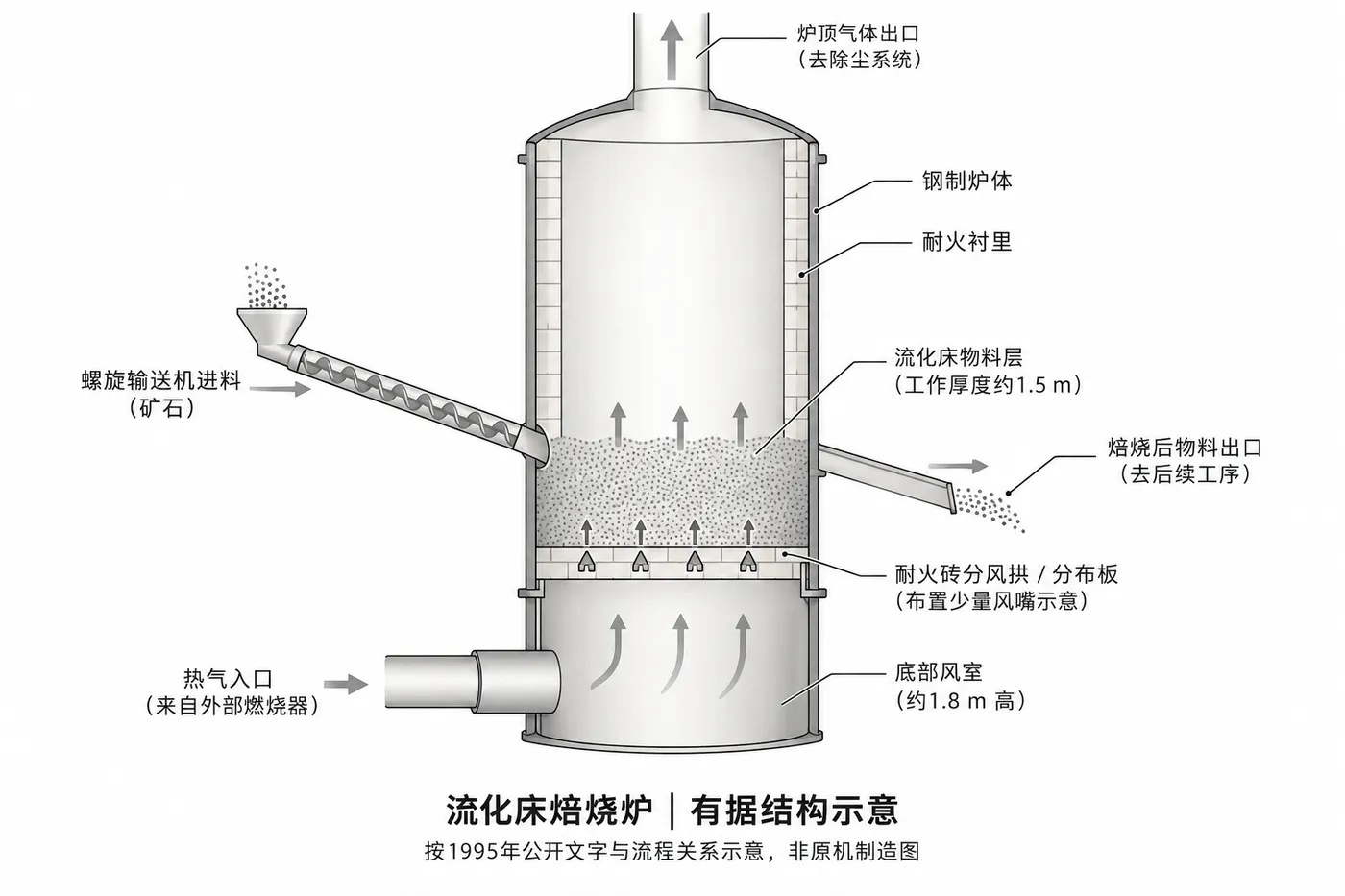
Select a model to jump to its component table; former and renamed designations are listed under “Historical names / renamings”.
| Model | Historical names / renamings | Period | Components |
|---|---|---|---|
| AMS single-stage fluidized bed roaster (site specifications) | single-stage fluosolids roaster (Golden Bear) | 1995-01 | 10 |
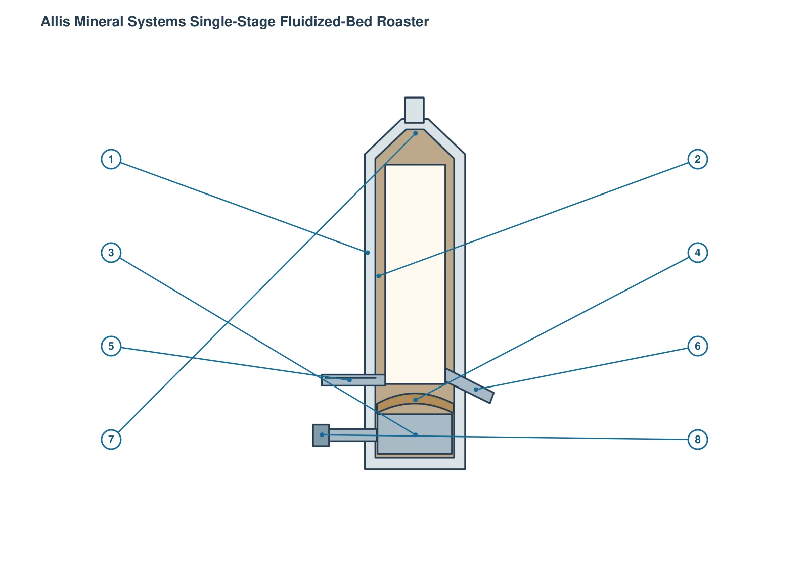
The numbers on the diagram correspond one to one with the rows below.
| No. | Component | Location | Applies to |
|---|---|---|---|
| 1 | Steel cylindrical furnace body | Outer cylindrical shaft | Golden Bear project single-stage AMS roaster design relationships |
| 2 | Refractory lining | Refractory lining inside shaft | Golden Bear project single-stage AMS roaster design relationships |
| 3 | Bottom windbox | Windbox below distributor arch | Golden Bear project single-stage AMS roaster design relationships |
| 4 | Refractory distributor arch | Between bed and windbox | Golden Bear project single-stage AMS roaster design relationships |
| 5 | Screw feed conveyor | Feed inlet above distributor arch | Golden Bear project single-stage AMS roaster design relationships |
| 6 | Discharge chute | Discharge 1.2 m above arch | Golden Bear project single-stage AMS roaster design relationships |
| 7 | Gas outlet cone cap | Top cone cap and gas outlet | Golden Bear project single-stage AMS roaster design relationships |
| 8 | External burner | Hot gas entry to windbox | Golden Bear project single-stage AMS roaster design relationships |
| Component |
|---|
| Air-distributor nozzle |
| Baked sand fluidized cooler and heat exchange tube (matching) |
Models with the same components are grouped together; select a group to open its component table.
| No. | Component | Location |
|---|---|---|
| 1 | Steel cylindrical furnace body | Original steel cylindrical shaft, vertical furnace body |
| 2 | Refractory lining | In the furnace body, 3.4m is the inner diameter of the lining |
| 3 | Bottom windbox | Bottom 1.8m, external hot gas mixed with metered cold air |
| 4 | Refractory air-distributor arch | Bridge-like brick structure between the air chamber and the upper hearth |
| 5 | Screw feed conveyor | Feeding point above the arch; supporting relationship, manufacturer is not clear |
| 6 | Discharge chute | The discharge material 1.2m above the arch enters the external roasting cooler |
| 7 | Top gas outlet cone cap | Original text to outlet cone cap overall internal height 11m |
| 8 | External burner (furnace system matching) | Air supply from air chamber; does not mean AMS self-made |
| Air-distributor nozzle | 153 air nozzles in the arch, each with 16 holes is the number on site | |
| Baked sand fluidized cooler and heat exchange tube (matching) | External baking sand cooling and combustion air reheating after the furnace |
The Fluidized-bed roaster is also documented under these designations: AMS single-stage fluidized bed roaster, single-stage fluosolids roaster.
The Fluidized-bed roaster is listed under the Allis Mineral Systems brand as: Fluidized-bed roaster. Period: 1995-01. Status: Historical model.
10 components are recorded, including: Steel cylindrical furnace body, Refractory lining, Bottom windbox, Refractory air-distributor arch, Air-distributor nozzle, Screw feed conveyor, Discharge chute, Top gas outlet cone cap and more. The full list with locations is in the components table on this page.
Send us a drawing or sample and tell us the equipment model and part name.
Provide the equipment model, drawing for engineering review and quotation. If service life or wear is a concern, describe the operating conditions as well.
Or contact us directly: +86 156 3797 3199
zzx@anranst.com
ANRANST provides customers worldwide with engineering assessment, production at certified foundries to the customer technical requirements, quality control and finished-part delivery for custom wear parts and industrial spares, with scope to support other custom industrial parts.
We review mating surfaces and interface dimensions and assess material, heat treatment and manufacturing feasibility.
Material grades and heat-treatment processes are specified order by order, stated in the technical agreement and tracked through production.
Drawing confirmation, material and process control, production tracking, inspection and acceptance coordination.
We coordinate manufacturing, quality confirmation, packaging and delivery of complete finished parts in a workable, closed-loop supply process.
Provide the equipment brand, complete model and serial number, part name, part number or drawing number, drawing revision, quantity, material requirements and duty. If identifiers are unavailable, send photographs and key dimensions.
Submit an Enquiry