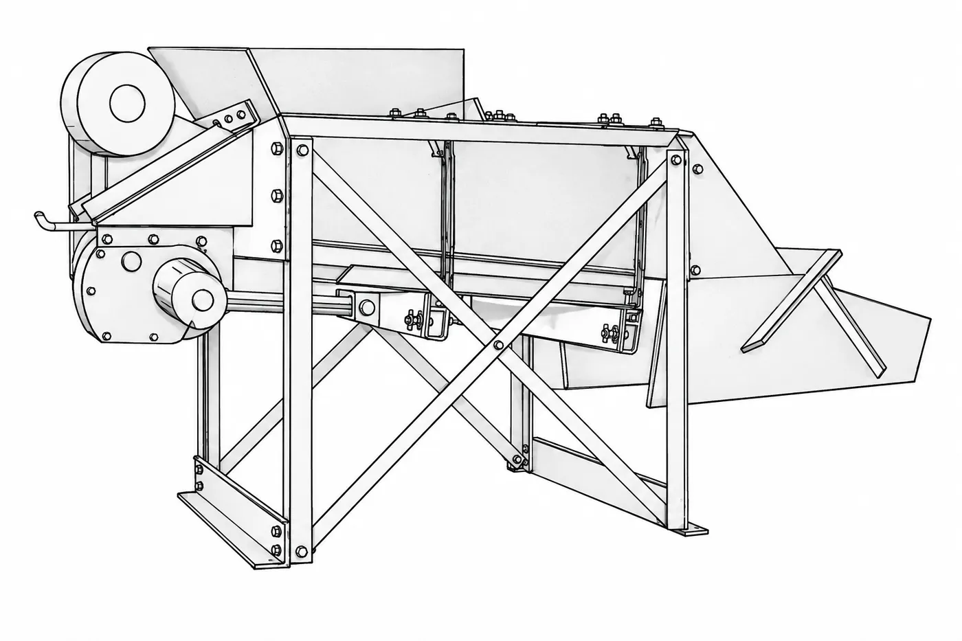
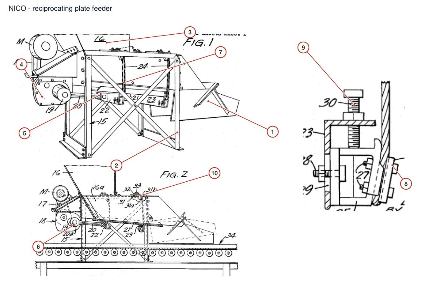
| 1 | Reciprocating feeding bottom plate | Tilt movement plate at the bottom of the hopper |
| 2 | Plate guide and support frame | Both sides and lower part of the reciprocating bottom plate |
| 3 | Hopper and inclined discharge wall | Above the patented Fig1-4 feeding bottom plate, the hopper tilts the discharge wall and opening |
| 4 | Fig1-4 Belt drive and gear reducer | Motor to crank output shaft |
| 5 | Eccentric crank connecting rod mechanism | Between the power end and the reciprocating bottom plate |
| 6 | Fig1-4 Heavy duty bearing at crank output end | Outside the reducer, supporting the crankshaft |
| 7 | Fig1-4 Pairs of suspended steel cables | Both sides of the feeding bottom plate, front and rear support on each side |
| 8 | Fig1-4 Steel cable clamp plate and fastening bolts | Bracket/frame steel cable fixed end |
| 9 | Fig1-4 Suspension height/tilt angle adjustment bolt | Upper suspension point with slotted adjustment bracket |
| 10 | Fig1-4 Arc rocker | Under the floor beam, in contact with the steel cable for load bearing |
| Reciprocating feeding tray | Lucky Friday on-site RH550 mine bin bottom; 3ft wide |
| Fig5-7 Differential hydraulic cylinder | The lower side of the hopper, connected to the reciprocating bottom plate |
| Fig5-7 Hydraulic pump, reversing valve and oil tank | Differential cylinder oil supply and return circuit |
| Fig5-7 Rigid suspension tie rod | Front and rear supports on both sides of the base plate |
| Fig5-7 Disc spring group | The lower end of the rear support rod; the upper end of the front support rod; both ends cannot be called the same assembly. |
| Fig8-11 Lateral rigid connecting rod | Between pairs of opposite rocking blocks, end bolt connection |
| Fig8-11 Differential drive cylinder | Power input terminal of ladder base plate |
| Fig5-7 Upper and lower bearings and rocking blocks | Between the suspension rod end and the hopper/floor beam |
| Fig5-7 Ladder feeding bottom plate | Below the hopper discharge port, the weight pushing surface |
| Fig8-11 Double arc rocker | The lower parts of the four corners of the base plate bear the base plate and load |
| Fig8-11 Slotted retainer and load-bearing guide surface | The frame and base plate are arranged upside down in pairs |